24
User and Service Manual
Doc # M010-004WWE July 2005
Gendex DenOptix® QST
Figure 4-15
User Manual and
Installation Guide
(Software and Hardware),
1 each
Figure 4-14
Power Cord, 1 each
Figure 4-16
USB 2.0 cable (6 ft, 2 m)
1 each
4.10 Hardware setup and connections
NOTE: Before you start the hardware setup, ensure that you have an acceptable com-
puter as outlined in Section 4.4. The computer must have a USB 2.0 port available.
Step 1: Pick a location using the guidelines from Section 4.8.
Step 2: Set up the computer and monitor per the manufacturer’s recommendations. Use an
ergonomic setup to minimize repetitive motion injuries.
Step 3: Turn the power on to the monitor and computer.
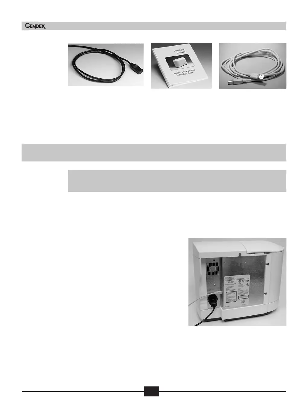
Step 4: Connect the device end of the USB 2.0
cable to the USB 2.0 connector on the
back of the DenOptix QST scanner.
Connect the scanner to a grounded
power outlet. Make sure the other end
of the USB 2.0 cable is connected to the
USB 2.0 port on the computer.
Step 5: Connect the computer to a network
if desired. Refer to your Imaging
Sof
tw
are User Manual and Installation
Guide for more information on how to
configure the Imaging Software in a
ne
twork.
S
tep 6:
T
urn the power on the scanner. The green light on the scanner should be lit at this
time. If it is no
t, follo
w t
he trouble shooting guidelines in Section 7.3.
Step 7: After the Windows operating system is loaded, a message indicating that a “New
Hardware” has been found will appear. Follow the on-screen instructions to final-
ize the installation.

 Loading...