26 Owner’s Manual for G4-ECO Light Tower
Operation
NOTE: All equipment or loads connected to the unit
MUST be properly grounded. If these appliances do not
have grounded plugs, a ground wire MUST be added
between the equipment and the grounding stud on the
receptacle panel per the National Electrical Code (NEC),
state and local regulations.
Engine Derating
All units are affected by derating for altitude and
temperature. Derating reduces the available power for
operating tools and accessories connected to the
receptacles. Typical reductions in performance are 2-4%
for every 1000 ft (305 m) of elevation and 1% per 10ºF
(5.6ºC) increase in ambient air temperature over 72ºF
(22ºC).
Shutting Down the Unit
Before shutting down the unit, check with the personnel
using power supplied by the receptacles and let them
know the power is going to be turned off. Verify the power
shut down will not create any hazards by accidentally
turning off equipment that needs to remain running
(pumps, compressors, etc.)
1. Remove all loads fr
om receptacles.
2. Use the controller Lamp 1-4 On/Off buttons to
switch all
lamps OFF.
NOTE: T
he lamps do not turn OFF simultaneously.
There is a delay between lights. The status LED above
the lamp switch will blink during this delay, and stop
blinking when the lamp switches OFF.
3. Press the controller Start/Stop button to stop the
e
ngine.
4. The engine icon
will blink during shutdown
and turn solid when the shutdown procedure is
complete.
5. Lower the mast.
6. Turn all breakers OFF.
7. Turn Utility/Off/Generator to the
OFF (O) position.
NOTE: Refer
to the engine operator’s manual for
extended storage procedures.
Towing the Unit
Prior to preparing the unit for towing:
• The unit must be shut down and allowed to cool.
See Shutting Down the Unit.
• Close and lock all hoods and doors.
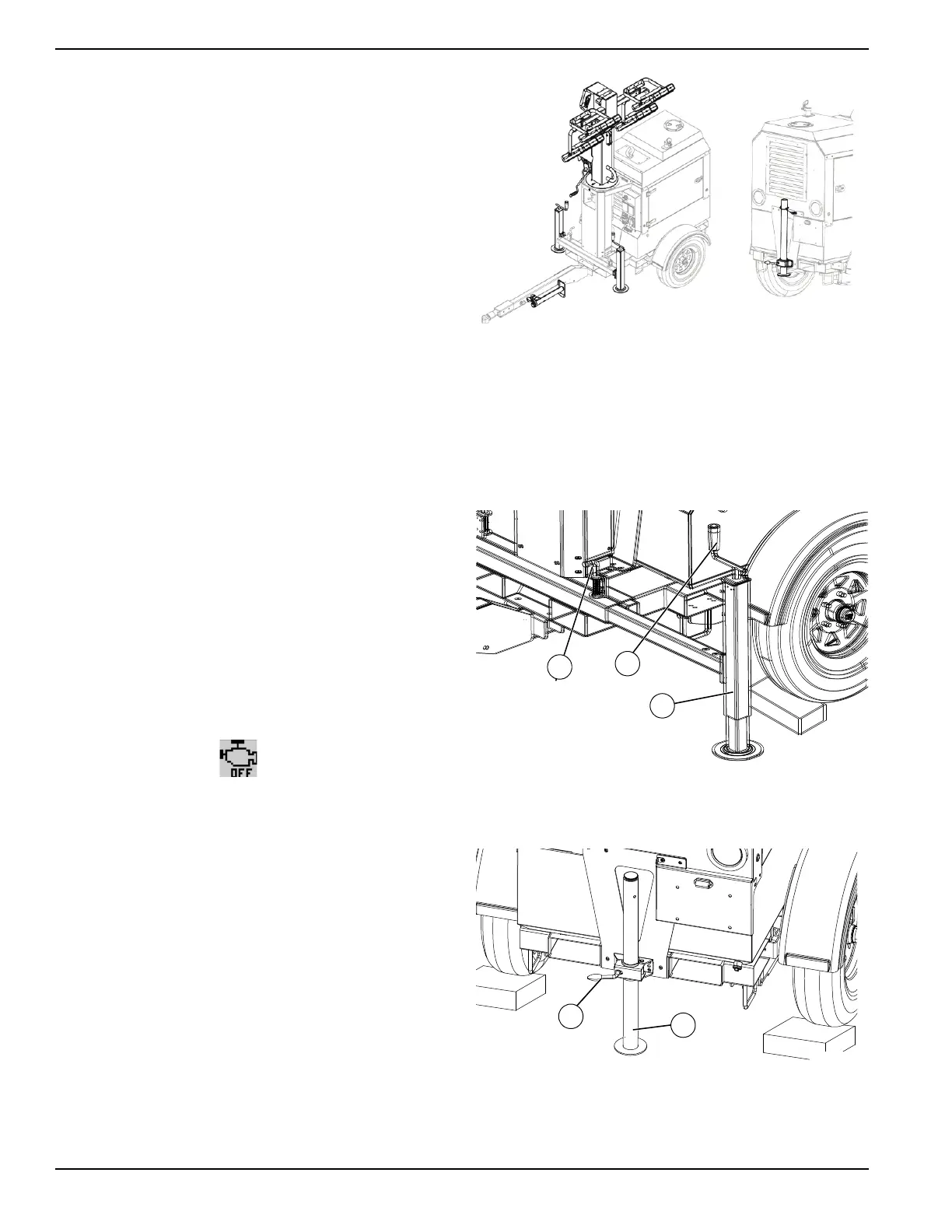
• See Figure 3-10. The mast and lights must be
slowed in the travel position as shown.
• Verify rear jack pin is locked.
Figure 3-10. Travel Position
To prepare the unit for towing:
1. Rotate mast so lights are in towing position.
2. See Figure 3-11. Use handle (A) to raise each
ou
trigger jack to uppermost position.
3. Pull locking pin (B) and slide each outrigger (C)
into
the trailer frame until the locking pins snap into
place.
Figure 3-11. Adjusting Outriggers
4. See Figure 3-12. Loosen handle (D) and raise rear
stabilizer (E) to uppermos
t position.
Figure 3-12. Adjusting Rear Stabilizer
5. Insert locking pin.


 To Next Page