11
Induction type motors (such as those that run the vehicle’s •
furnace fan, refrigerator, air conditioner, etc.) need about 2-1/2
times more watts of power for starting than for running (for a
few seconds during motor starting). Be sure to allow for this
when connecting electrical loads to the generator. First, figure
the watts needed to start electric motors in the system. To that
figure, add the running wattages of other items that will be oper-
ated by the generator.
Do not apply heavy electrical loads for the first two or three •
hours of operation.
2.8 PROTECTION SYSTEMS
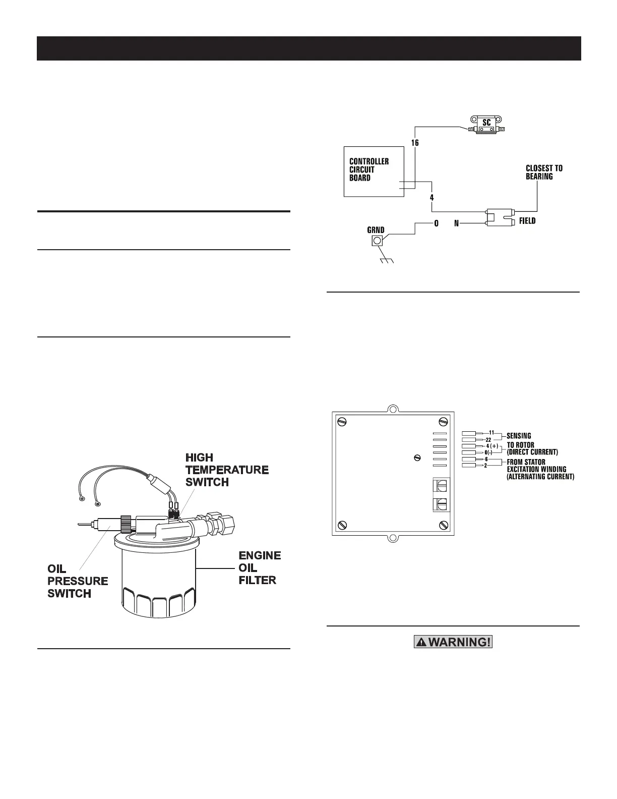
2.8.1 LOW OIL PRESSURE SWITCH
This switch (Figure 2.3) has normally closed (N.C.) contacts that
are held open by engine oil pressure during cranking and operat-
ing. Should oil pressure drop below a preset level, switch contacts
close, and the engine automatically shuts down. The unit should
not be restarted until oil is added.
2.8.2 HIGH TEMPERATURE SWITCH
This switch (Figure 2.3), which has normally open (N.O.) contacts,
is mounted near the oil filter. The contacts close if the tempera-
ture should exceed approximately 270º F (132º C) for gasoline
models, and 284° F (140° C) for LP models, initiating an engine
shutdown.
Figure 2.3 – Low Oil Pressure and
High Temperature Switches
2.8.3 FIELD BOOST
The Controller Circuit Board houses a field boost diode and resistor
that are not part of the automatic choke circuit. These two compo-
nents are part of a “field boost” circuit (Figure 2.4). During engine
cranking only, a positive DC (battery) voltage is delivered through
a diode, resistor, brushes, slip rings, and the generator rotor.
Application of this voltage to the rotor “flashes the field” whenever
it is started. Flashing of the field each time the generator starts
makes sure that a sufficiently strong magnetic field is available to
produce “pickup” voltage in the stator windings.
Figure 2.4 – Field Boost Circuit
2.8.4 OVERVOLTAGE PROTECTION
A solid-state voltage regulator (Figure 2.5) controls the generator’s
AC output voltage. This regulator supplies an excitation current to
the rotor. By regulating the rotor’s excitation current, the strength
of its magnetic field is regulated and, in turn, the voltage delivered
to connected electrical loads is controlled. When the AC frequency
is 60 Hertz, voltage is regulated at 115 volts.
Figure 2.5 – Solid State Voltage Regulator
The voltage regulator also incorporates a “voltage surge protection
circuit.” This circuit prevents troublesome surges in the generator
AC output voltage. Voltage surge is a common cause of damage
to electronic equipment.
2.8.5 OPERATION IN HIGH GRASS OR BRUSH
Never operate the generator while the vehicle
is parked over high grass, weeds, brush, leaves
or any other combustible substance. Such
materials can ignite and burn from the heat of
the exhaust system. The generator exhaust sys-
tem becomes extremely hot during operation
and remains hot for a long time after it has shut
down.
Operation
 Loading...