29
2.3.2 TESTING THE INSTALLATION
The manufacturer recommends testing the installation to be sure
adequate cooling airflow is available to the unit before placing the
unit into service. If the unit shows signs of overheating, enlarge the
air openings. Never place a unit into service until absolutely certain
that cooling and ventilation is adequate.
NOTE:
The installation must be tested, especially if bringing in air from
below the generator set.
2.4 GASOLINE FUEL SYSTEM
Gasoline is highly flammable, and its vapors
are explosive. Comply with all codes, standards
and regulations pertaining to gasoline fuel sys-
tems used in recreational vehicle generators.
Properly install and maintain the fuel system
and keep it entirely free of leaks. Gasoline
vapors must not enter the vehicle interior.
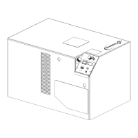
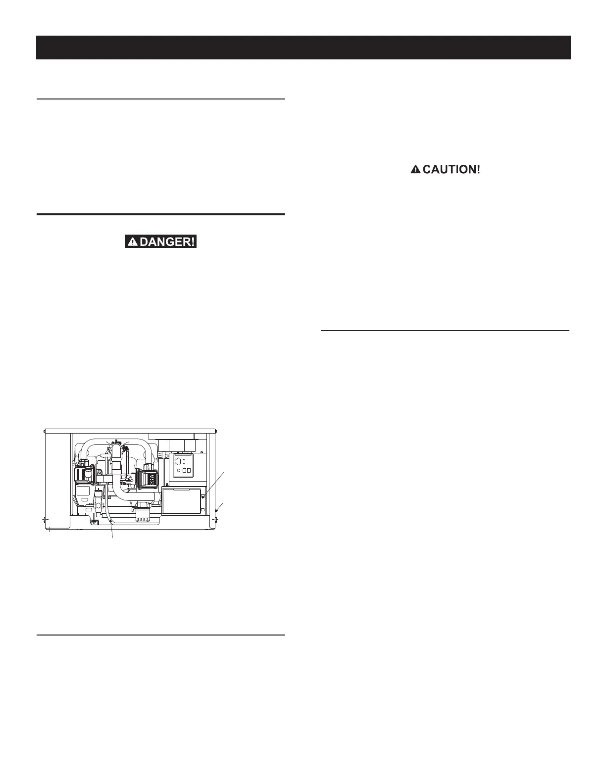
The installation of a gasoline fuel system (Figure 2.10) for a
recreational vehicle generator set must comply with applicable
codes, standards and regulations. The entire fuel system must be
completely free of leaks. There must be no possibility of gasoline
vapors entering the vehicle interior.
Figure 2.10 – Generator Fuel System
IF GENERATOR DOES NOT START, REMOVE
AND INSPECT FUSE.
(SEE OWNER'S MANUAL TROUBLE SHOOTING
GUIDE.)
PRESS PRIME SWITCH FOR 10 SECONDS BEFORE STARTING. WHEN STARTING, DO
NOT PRESS START BUTTON LONGER THEN 15 SECONDS PER ATTEMPT.
STOP
PRIME
CONTROL CENTER
7.5A
FUSE
START
FUEL
CIRCUIT
BREAKER
BREAKER
CIRCUIT
(OR ANNUALLY)
CHANGE EVERY 400 HOURS.
FUEL FILTER P/N:
PREFILTER P/N:
CONTACT THE GUARDIAN SERVICE LOCATOR AT 1-800-333-1322.
WHEN SERVICE OR PARTS ARE NEEDED IN THE USA OR CANADA,
SPARK PLUG P/N:
OIL FILTER P/N:
AIR FILTER P/N:
INSPECT & CLEAN
PLUGS EVERY 100 HOURS.
REPLACE PLUGS EVERY
500 HOURS. (IF NECESSARY)
CHECK DAILY
(SAE VISCOSITY)
1.8L/1.9QT
HOURS. (OR ANNUALLY)
SAE 30 OR 10W-30
5W-30 OR 5W-20
PERFORM MORE OFTEN IN DUSTY CONDITIONS
CHANGE EVERY 100
EVERY 250 HOURS.
REPLACE ELEMENT
EVERY 100 HOURS.
CLEAN PREFILTER
TEMPERATURE:
-20°F TO 40°F
40°F AND HIGHER
WITH FILTER:
OIL CAPACITY
OIL & OIL FILTER:
*
AIR FILTER:
REPLACEMENT
INFORMATION:
FUEL FILTER:
MAINTENANCE SCHEDULE
SPARK PLUGS:
OIL LEVEL:
*
*
*
SERVICE ACCESS PANEL
AIR FILTER LOCATED BEHIND PANEL.
0D4511
087769
072347
070185
0D9723
Fuel Pump
(Behind Access
Cover)
Fuel Filter
(Side of Unit)
Fuel Line
Factory installed generator fuel system components include (a)
fuel filter, (b) 12-volt DC electric pump, (c) engine carburetor, and
(d) interconnecting lines and fittings. Connect a fuel supply line
to the fuel filter inlet. Use a flexible length of approved fuel hose
between the fuel filter inlet connection and rigid fuel lines.
2.4.1 FUEL TANK
Either the generator must share the vehicle engine's fuel tank, or a
separate fuel tank for the generator set must be installed. All fuel
tanks installed on the vehicle must be constructed, installed and
restrained so they comply with applicable codes, standards and
regulations. The generator has an evaporative emissions port to
evacuate accumulated gasoline vapors whtn necessary.
If the generator is to share the vehicle engine's tank, separate
fuel pickup tubes are required for the engine and the generator.
The manufacturer recommends that the fuel pickup tube be two
to three inches (51 to 76 mm) shorter than the vehicle engine's
pickup tube. This prevents the generator from depleting the entire
fuel supply during prolonged generator operating periods.
n
Do NOT tie the generator fuel supply line into
the vehicle engine fuel supply line. If this is
done, the generator will be starved of fuel
when both engines are operating at the same
time. Also, while the vehicle engine is not run-
ning, generator operation may drain the vehicle
engine supply line, making it difficult to start
the vehicle engine.
An evaporative emissions port model 05750 has a 5/16" hose
barb provided for connection to a carbon canister as necessary
for specific applications.
2.4.2 GENERATOR FUEL SUPPLY LINE
Rigid Fuel Lines
Those lines used to supply fuel from a tank to the generator must
comply with applicable codes, standards and regulations. The fol-
lowing general rules apply to rigid fuel lines:
Rigid lines should be of annealed, seamless, drawn aluminum •
or steel.
Lines and fittings must comply with SAE J512F, “Standard •
Automotive Fittings,” or with ANSI B126.26 (latest edition).
Route the fuel line so that at least 2 inches (51 mm) of clear-•
ance is maintained between the line and any exhaust system
parts.
Do not attach electrical wiring to fuel lines. Route the wiring so •
it cannot come into contact with any fuel line.
Route fuel lines so if they leak, fuel does not drip onto any •
electrical or exhaust system parts.
Use nonferrous metal straps without sharp edges to secure •
fuel lines.
Flexible Fuel Line
Use an approved flexible length of fuel hose between the generator
fuel inlet connection and rigid fuel lines. This prevents breaking of
the line caused by vibration, shifting, settling or movement. The
following rules apply:
The flexible hose must comply with SAE J30R7, “Standard for •
Fuel and Oil Hose.” It must be approved for use with gasoline
and low permeability.
The hose should be at least 6 inches (152 mm) longer than •
is needed to prevent the hose from rupturing if the generator
shifts or settles.
Installation
 Loading...