Maintenance
32 Owner’s Manual for Stationary Industrial Generators
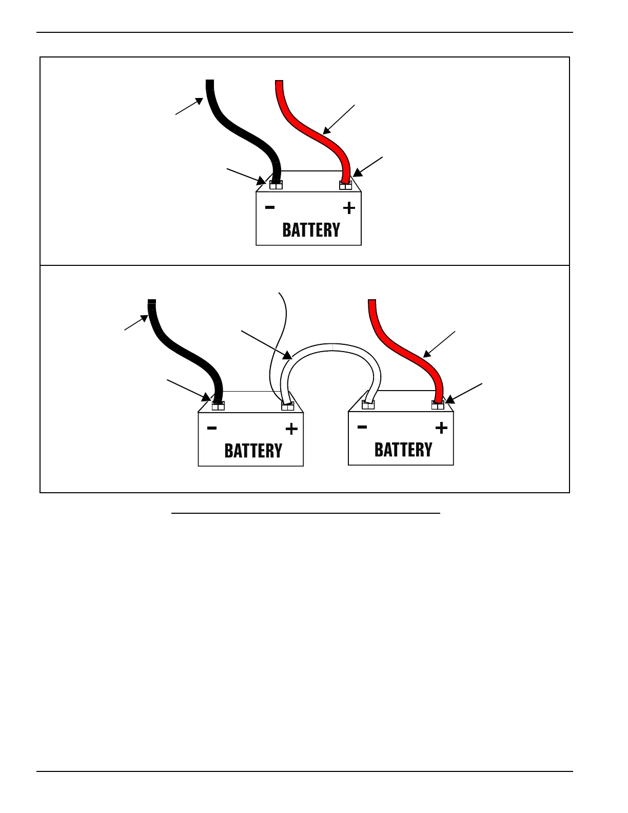
Figure 4-2. Battery Cable Connections
24VDC System
1. Connect the red battery cable from the starter contactor to the positive (POS or +) post of battery A.
2. Connect the black battery cable to the frame ground to the negative (NEG or -) post of battery B.
NOTE: On 24V gaseous units, center tap wire number 13 between the batteries as shown in Figure 4-2.
3. Connect either a black or red jumper cable from the negative (NEG or -) post of battery A to the positive
(POS or +) post of battery B.
Final Instructions
1. Install the ATC style fuse in the battery charger.
2. Install the 10A fuse in the generator control panel.
3. Turn on the utility power supply to the battery charger circuit.
4. If the unit was previously operational, turn the AUTO/OFF/MANUAL switch on the generator control panel to
AUTO.
Damage will result if the battery connections are made in reverse.
AB
12VDC12VDC
Black Lead
To Frame
Black (-)
Red (+)
Red or Black
Jumper
Red Lead
From Starter
Contactor
12VDC
Red (+)
Red Lead
From Starter
Contactor
Black (-)
Black Lead
To Frame
12VDC System
24VDC System
Wire 13
 Loading...