25
8. The grounding that is normally in the main panel must be
accomplished in the Power Manager Load Shed transfer
switch and must be disconnected in the existing distribution
panel. Refer to the National Electrical Code (NEC) for
complete information on grounding and bonding.
BATTERY CHARGER INSTALLATION
1. The battery charger is factory installed in the transfer switch.
ELECTRICAL CONNECTIONS
1. Connect the utility power leads from the meter to the Utility
circuit breaker in the transfer switch.
2. Connect the generator power leads to the E1 and E2 terminals
on the transfer switch contactor.
3. Connect the customer non-priority load leads to the E1 and E2
terminals on the load shed contactor.
4. Be careful to support the lugs and torque the lugs in the
transfer switch to the specifications shown in the transfer
switch Owner’s Manual.
5. Neutral wires from the utility, generator and shedding panel
are connected to the same neutral lug in the switch.
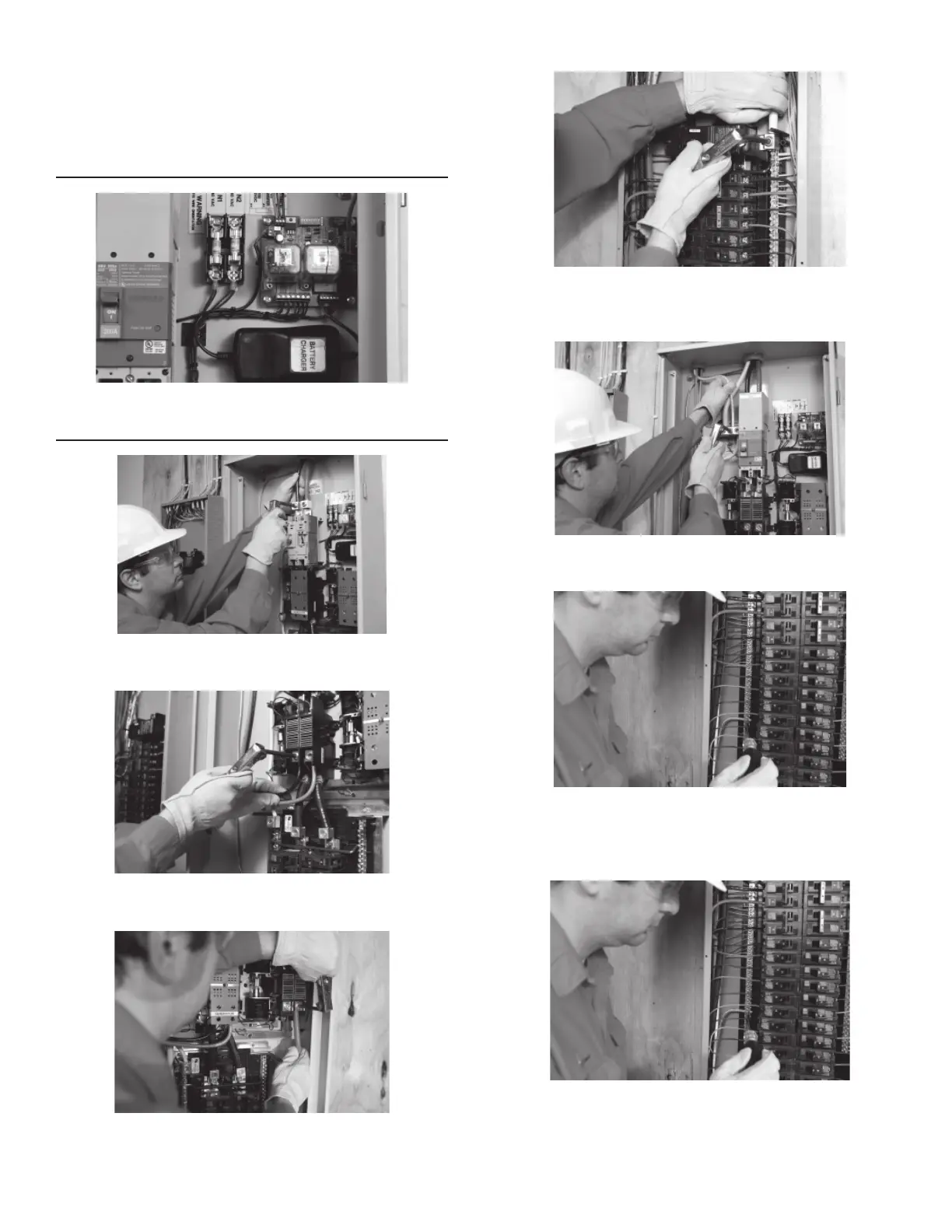
6. In this step, move priority load circuits, which will always
be backed up by the generator, from the existing electrical
distribution panel to the 16 circuit load center in the Power
Manager Load Shed switch.
7. Select a priority circuit to be backed up and remove the power
lead from the breaker.
 Loading...