20
3. Using the ring lugs provided and the wire specified in the
PowerMaster Technical Manual, connect one end of new
power leads to one of the contactors in the load controller.
4. Connect the other end of the new power leads to the
appliance breaker in the distribution panel.
5. Connect the power leads that were removed from the
appliance breaker to the load terminals in the controller.
6. Now run 24 volt control wires from the air conditioning circuit
to the terminal strip in the controller.
7. The auxiliary switches that came with the controller must be
installed in the transfer switch. These switches ensure that the
controller will only disconnect the selected appliances when
utility power is off and the generator is running. Refer to the
Technical Manual for specific instructions for installing the
auxiliary switches.
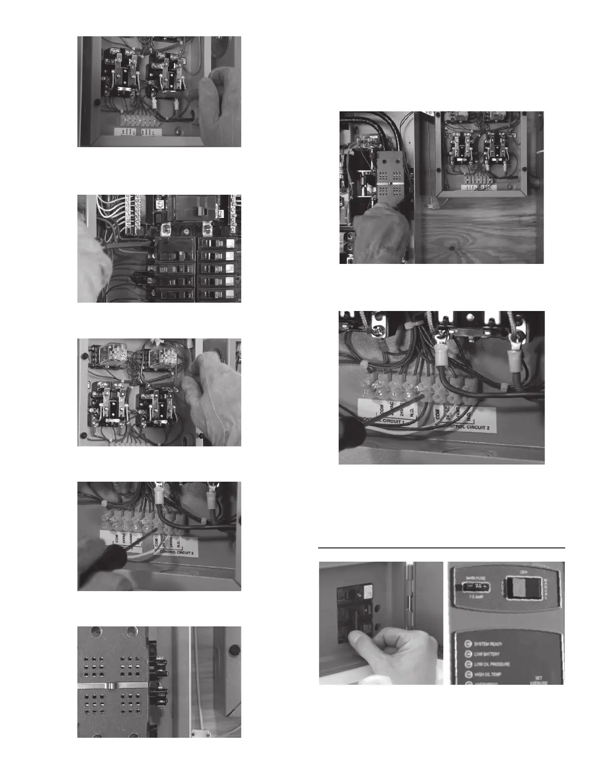
8. Connect one end of two control wires to the COMMON and
NORMALLY OPEN pins on the generator side of the transfer
switch.
9. Connect the other ends of the control wires to the COMMON
and NORMALLY OPEN positions of the selected control circuit
in the controller.
If moving a second load to the controller, follow the same
procedure.
OPERATIONAL TESTING
1. Switch the generator’s main circuit breaker OFF and put the
mode switch in the OFF position.
 Loading...