33
8. Connect the control wires from the generator to the load
center operator. Connect the 23 wire to the XFER terminal,
15B to the BAT+ terminal, and 0 to the BAT- terminal.
9. Connect the voltage sensing wires to the sense breaker. This
is the 2 pole breaker directly above the operator on the right
side of the load center. Connect N1 to one pole of the breaker,
and N2 to the other.
10. Switch ON the main utility breaker if not already on and switch
on the utility supply breaker for the priority circuits. Make sure
utility voltage at the load center is correct. Refer to NFPA 70E
for the safety equipment required when working inside a live
load center.
OPERATIONAL TESTING
1. The following operational tests are meant to be performed
with a fully installed system. If the GenReady panel
was installed without a generator, these tests cannot be
performed.
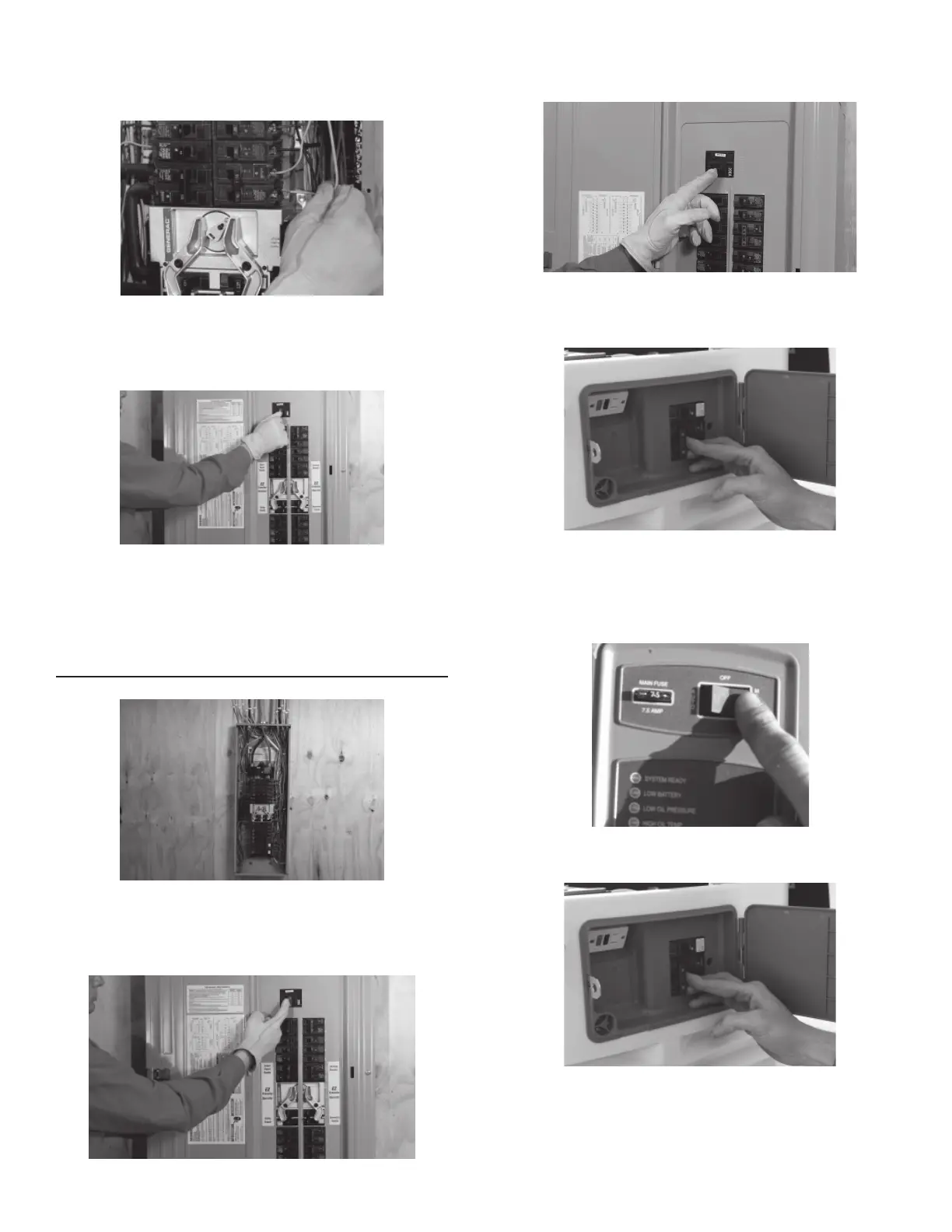
2. Switch the generator’s main circuit breaker OFF and put the
mode switch in the OFF position.
3. Switch the main utility breaker OFF and place all of the
individual protected branch circuit breakers (located below the
transfer operator) in the OFF position.
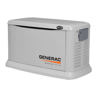
4. Manually switch the generator circuit breaker (just below the
transfer operator) to the ON position. This will also move the
utility feed circuit breaker to the OFF position.
NEVER MOVE THE LOAD CENTER FEED BREAKERS
MANUALLY WHEN LOADS ARE CONNECTED.
5. With the generator’s main breaker OFF, put the mode switch in
MANUAL to start the engine.
6. Allow the engine to warm up, then switch the generator’s
main breaker to the ON position. The generator is now
supplying electricity to the lower half of the load center but is
not carrying any load.
 Loading...