7
Figure 7 — Spark Plug Gap
CLEANING SPARK ARRESTOR SCREEN
If the engine exhaust muffler has a spark arrestor screen, inspect
and clean the screen every 100 hours of operation or once each
year, whichever comes first.
NOTE:
If using the equipment on any forest-covered, brush-covered or
grass-covered unimproved land, it must have a spark arrestor.
The spark arrestor must be maintained in good condition by the
owner/operator.
Clean and inspect the spark arrestor screen as follows:
Inspect the screen and replace if it is torn, perforated or otherwise
damaged. DO NOT USE a defective screen. If the screen is not
damaged, clean it with a commercial solvent.
If the spark arrestor is found to be damaged or defective, replace it.
SERVICE AND ADJUSTMENTS
ENGINE SPEED
The engine speed was properly adjusted at
the factory and should require no additional
adjustment. Do not attempt to change engine
speed. If the engine is running too fast or too
slow, take the engine/equipment to an autho-
rized service center for repair and adjust-
ment. CHANGING THE ENGINE GOVERNED
SPEED WILL VOID THE ENGINE WARRANTY.
The operating speed of this engine is maintained by a mechanically
controlled governor. DO NOT try to adjust the governed speed set-
ting for the following reasons:
• Operating the engine at high engine speeds is dangerous and
increases the risk of personal injury or damage to the equip-
ment.
• Operating the engine at low engine speeds with heavy loads
may shorten the engine’s life.
CARBURETOR ADJUSTMENTS
The carburetor is pre-set at the factory. The carburetor should not
be tampered with because it would violate EPA and CARB regula-
tions and VOID THE EMISSION CONTROL SYSTEM WARRANTY.
CHECKING AND ADJUSTING VALVE CLEARANCE
Check valve lash and adjust (if necessary) after the first 50 hours
of operation and every 100 hours thereafter.
IMPORTANT: If not qualified for doing this procedure or the proper
tools are not accessible, please take the engine/equipment to the
nearest Dixie Chopper dealer to have the valve clearance adjusted.
This is a very important step to insure a long life for the engine.
To adjust valve clearance:
• Make sure the engine is at room temperature.
• Remove spark plugs and make sure that the spark plug wires
are out of the way.
• Remove the four screws attaching the valve cover with a 10 mm
wrench or socket.
• Make sure the piston is at Top Dead Center (TDC) of its com-
pression stroke (both valves closed). To get the piston at TDC,
remove the intake screen at the front of the engine to gain access
to the flywheel nut. Use a ratchet and a 36 mm socket to rotate
the engine. While watching the piston through the spark plug hole,
the piston should be observed moving up after the intake valve is
closed. The piston is at TDC when it is at its highest point of travel.
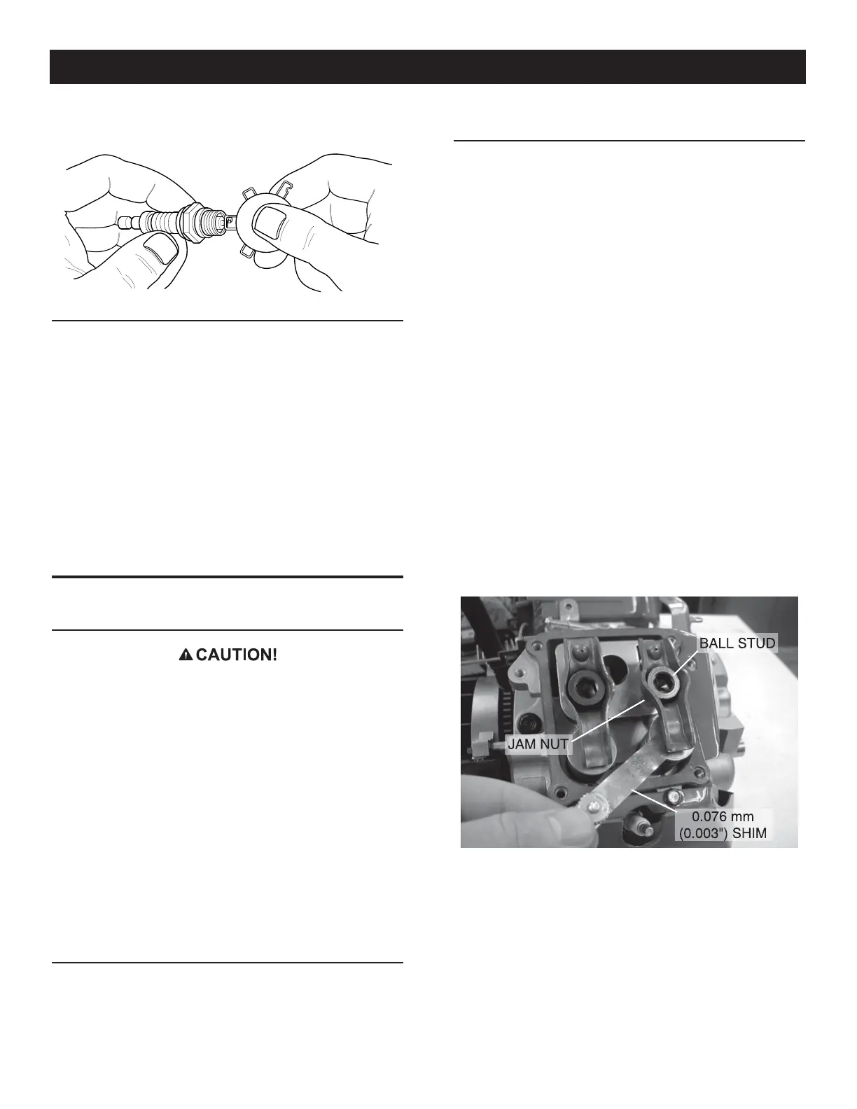
• Loosen the rocker jam nut (Figure 8). Use an 10mm allen
wrench to turn the pivot ball stud while checking clearance
between the rocker arm and the valve stem with a feeler gauge.
Correct clearance is 0.002-0.004 inch (0.05-0.1mm) for both
intake and exhaust.
Figure 8 — Adjust Valve Clearance
NOTE:
The rocker arm jam nut must be held in place as the pivot ball
stud is turned.
When valve clearance is correct, hold the pivot ball stud in
place with the allen wrench and tighten the rocker arm jam
nut. Tighten the jam nut to 168 in/lbs. (19 Nm) torque. After
tightening the jam nut, recheck valve clearance to make sure
it did not change.
• Install new valve cover gasket.
• Install the valve cover and torque to 60 in/lbs (6.8 Nm).
Maintenance

 Loading...


