2-2
SECTION 2: IGNITION
4. Repeat for second armature.
5. Adjust armature air gap.
ADJUST ARMATURE AIR GAP:
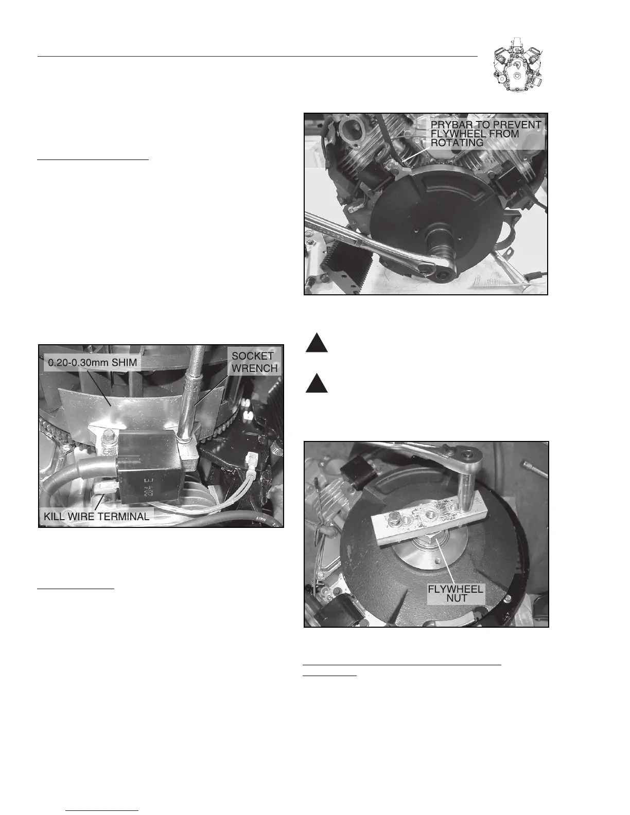
1. Rotate flywheel until magnet is under armature
laminations.
2. Place thickness gauge, 0.20-.30 mm (.008"-.012") between
magnet and armature laminations, Figure 2-3.
3. Loosen mounting screw so magnet will pull armature down
against thickness gauge.
a. Torque screws to 12.2 Nm (9 ft. Ibs.).
4. Rotate flywheel to remove thickness gauge.
5. Repeat for second armature.
Note: Route armature ground wire over breather tube
and away from the flywheel.
Figure 2-3. Adjusting Air Gap
FLYWHEEL
REMOVE FLYWHEEL:
1. Remove flywheel nut and washer, Figure 2-4.
2. Remove fan retainer and fan.
4. Reinstall flywheel nut. Turn nut down flush with top of
threads.
5. Install flywheel puller.
6. Tighten puller screws equally until flywheel loosens,
Figure 2-5.
Figure 2-4. Removing Flywheel Nut
Caution: Flywheel puller bolts may damage lighting
coil if turned in too far.
Caution: DO NOT strike flywheel with a hard object
or a metal tool as this may cause flywheel to shat-
ter in operation. Always use approved flywheel
removal tools.
Figure 2-5. Removing Flywheel
INSPECT FL
YWHEEL KEY, KEYWAYS, FLYWHEEL AND
CRANKSHAFT:
Check flywheel key for damage. Check flywheel for cracks
or keyway damage. Also check crankshaft keyways and taper
for damage, Figure 2-6. Replace crankshaft, if damaged.

 Loading...


