SECTION 5: CYLINDER HEAD AND VALVES
5-4
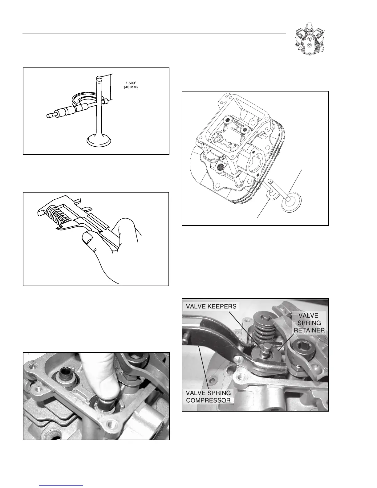
Figure 5-11. Measure Valve Stem Diameter
5. Check valve springs for free length (Figure 5-12).
Replace if free length is less than 36.5 mm (1.437 inches).
Figure 5-12. Check Valve Springs
ASSEMBLE CYLINDER HEAD
1.Install new valve stem seals.
a. Oil inner surface and lip of valve stem seal.
b. Press seal on to intake valve guide bushing until it bottoms
(Figure 5-13).
Figure 5-13. Install Valve Stem Seals
2.Install valves (Figure 5-14).
Note: Lightly coat valve stems with oil or Spectra Lube
Red before installing valves. Be sure lubricant is not on
valve face, seat or end of valve stem.
Figure 5-14. Install Valves
3. Place a shop rag or short section of rubber fuel line under
valves inside combustion chamber to hold valve in place
while compressing spring.
4. Install valve springs and valve spring retainers over valve
stems.
5. Compress valve spring and install keepers (Figure 5-15).
Figure 5-15. Compress valve spring and install keepers
6. Repeat procedure for other valves.
7. Set guide plate in place and loosely install rocker arm
assemblies (ball stud, rocker arm and jam nut).
8. Repeat Step 7 for other head.

 Loading...


