5-2
SECTION 5: CYLINDER HEAD AND VALVES
Note: Mark components so that they may be reassem-
bled in their original position.
REMOVE ROCKER ARMS:
1. Unlock jam nuts and remove two ball studs and rocker arm
assemblies (see Figure 5-3).
2. Remove push rods and identify each.
Note: The valve push rods are aluminum. Mark push
rods for identification to prevent interchanging.
Figure 5-3.
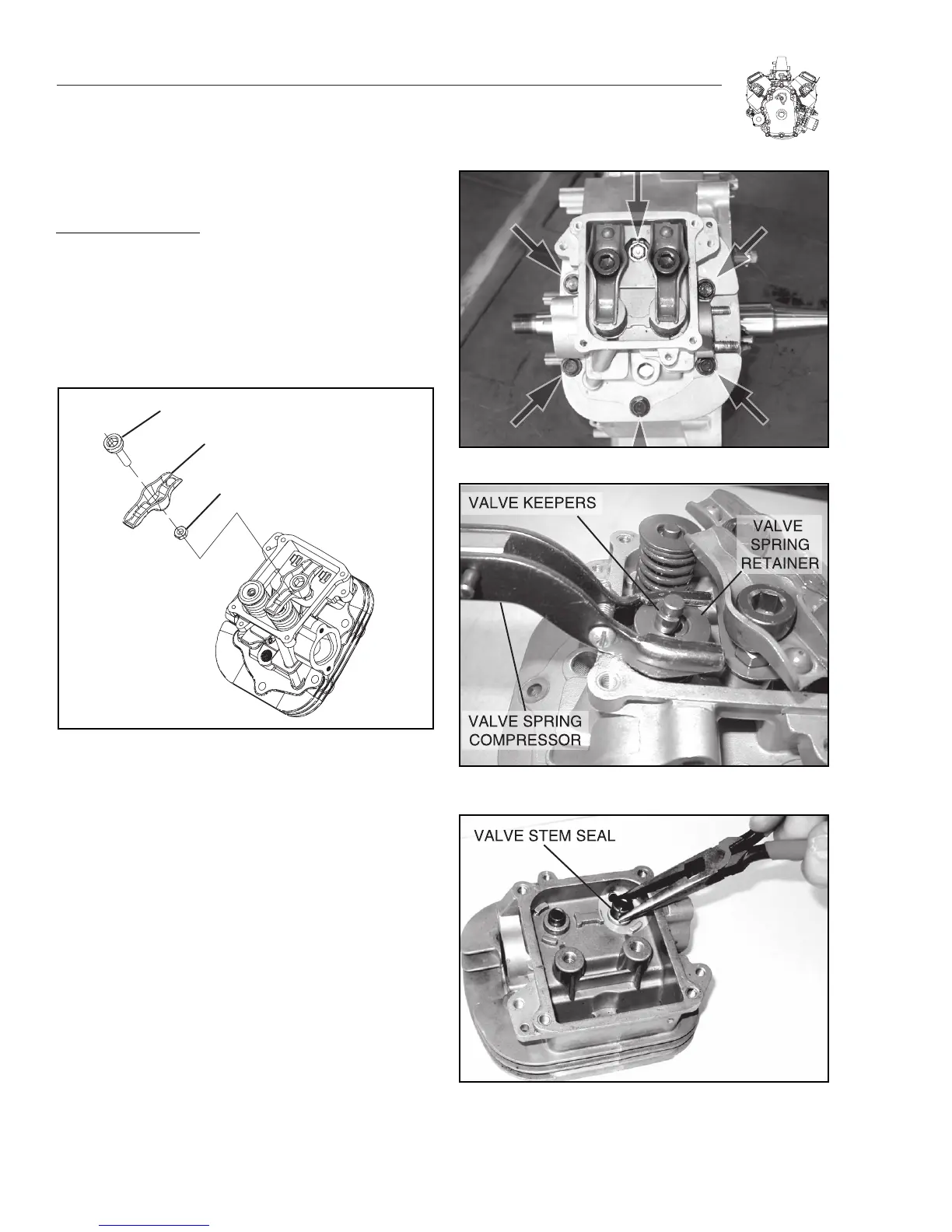
3. Remove head bolts and cylinder head (Figure 5-4).
a. Discard gasket.
4. Repeat Steps 1-3 for other cylinder head.
DISASSEMBLE CYLINDER HEAD
1. Place a shop rag or short section of rubber fuel line under
valves inside combustion chamber to hold valve in place
while compressing spring.
2. Hold down valve spring retainer by hand or with a valve
spring compressor (Figure 5-5). Remove the following:
a. Valve spring keepers
b. Valve spring retainer
c. Valve spring
d. IN and EX valves
3.Remove and discard valve stem seals (Figure 5-6).
Figure 5-4. Remove Cylinder Head
Figure 5-5. Removing Retainers
Figure 5-6. Removing Valve Stem Seals

 Loading...


