2-4
SECTION 2: IGNITION
1. Insert RED test lead into receptacle in meter.
2. Insert BLACK test lead into the “COM” receptacle in meter.
3. Rotate selector to (Diode Test) position.
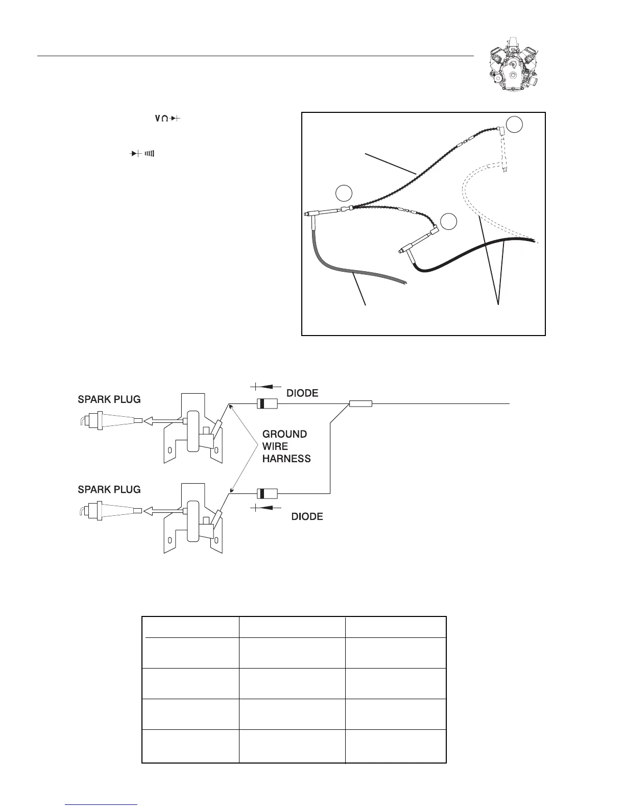
4. Insert RED test lead clip into connector "A" (Figure 2-10).
Leave attached for remainder of test.
5. Touch BLACK test lead probe to terminal "B."
a. If meter "Beeps" once, diode is OK.
b. If meter makes a continuous tone, diode is defective
(shorted). Replace ground harness.
c. If meter displays "OL," diode is defective (open). Replace
ground harness.
6. Now repeat test for terminal "C." Results must be the same.
See “Diode Failure Diagnosis” below.
Figure 2-10. Testing Ground Wire
SWITCH ON TURNED OFF CAUSE
Engine Runs Shuts Off OK 1 Closed Diode
On 1 Cylinder
Engine Runs Only One Cylinder 1 Open Diode
(Both Cylinders) Shuts Off
Won't Run 2 Closed Diodes
(No Spark)
Engine Runs Engine Won't Shut Off 2 Open Diodes
(Both Cylinders)
Figure 2-11. Engine Wiring Harness
DIODE FAILURE DIAGNOSIS

 Loading...


