4-2
SECTION 4: GOVERNOR CONTROLS AND GOVERNOR
8. Slide the arm in until the thrust washer is tight.
9. Slide the lower bushing down and into it’s holder, then install
the upper e-clip.
ASSEMBLE:
1. Clean any old gasket material from the crankcase and
cover mating surfaces.
2. Be sure that the new oil passage o-ring is in place.
3. Put a new gasket on the crankcase.
4. Slide the crankcase cover back on the crankcase.
Note: Hold the governor arm in the counter-clockwise
position while installing. Also, make sure that the swing-
ing arm bracket goes in place.
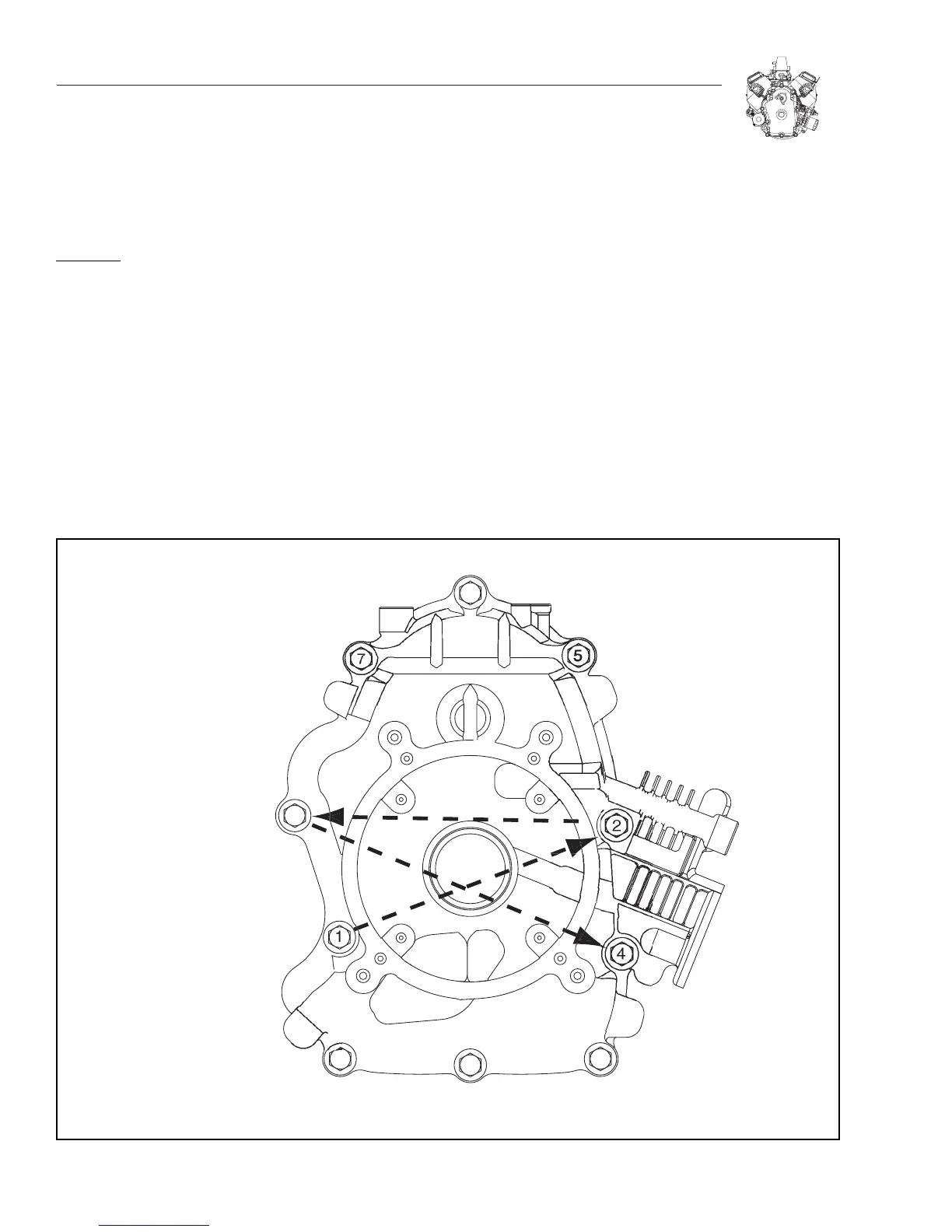
5. Start all of the crankcase bolts, and then torque them to
35 ft. lbs., following the proper torque sequence.
6. Reconnect the ball joint on the swing arm.
7. Place the governor lever on the governor arm, with the
spring in the 4th hole out.
8. Perform a static governor adjustment.
9. Reconnect the ground wire to the oil pressure switch.
10. Reattach the oil cooler to the blower housing.
STATIC GOVERNOR ADJUSTMENT
1. Loosen the clinching screw on the governor lever.
2. Rotate the governor arm clockwise and hold governor
lever in WOT position.
3. While holding this position, torque the clinching screw to
11.3 Nm (100 in. lbs.).
4. Check to make sure that the throttle travels from WOT to
IDLE. If it doesn't, the governor needs to be reset again.

 Loading...


