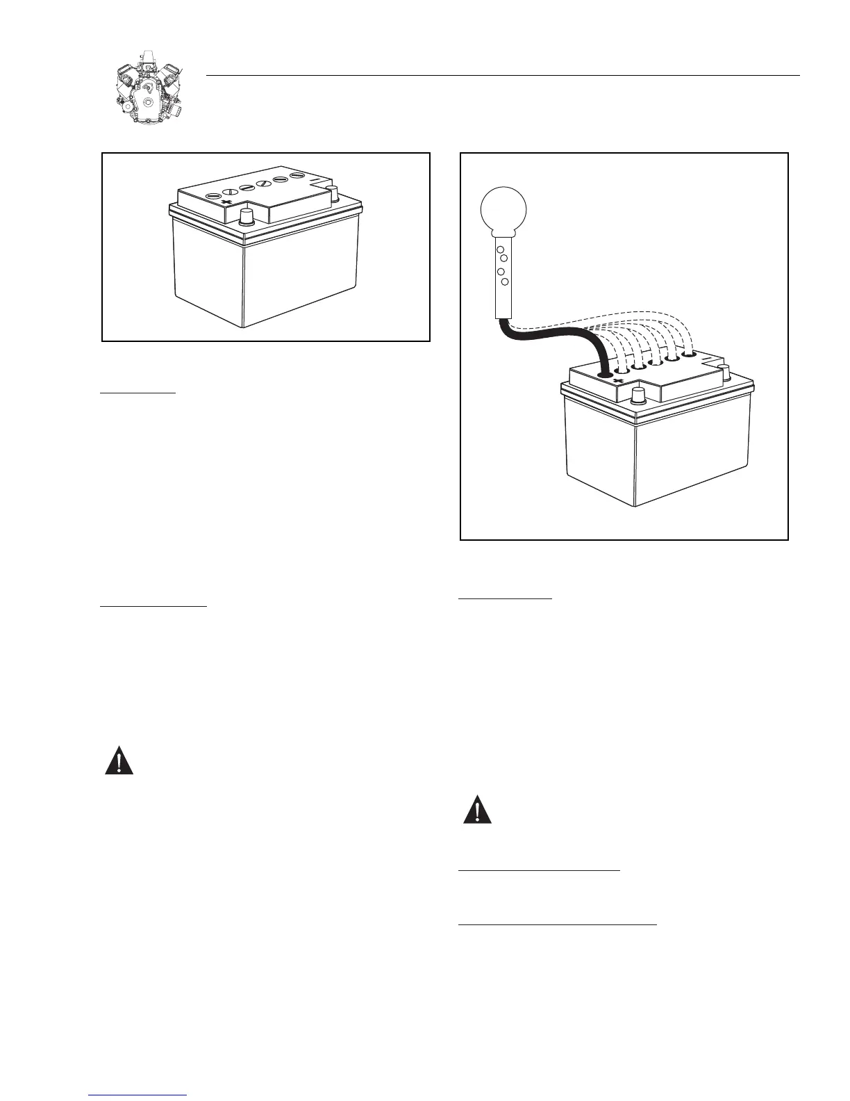
Figure 6-4. Typical Battery
INST
ALLA
TION:
1. Before installing battery, connect all equipment to be
operated.
2. Place battery in holder with flat base. Tighten holder down
evenly until snug. DO NOT overtighten.
3. Connect positive terminal to positive post FIRST to prevent
sparks caused by accidental grounding. Tighten connec-
tors securely.
4. Connect negative terminal to negative battery terminal.
Tighten connectors securely.
CHECKING BATTERY:
1. Physical check – clean if necessary.
a. Corrosion
b. Dirt
c. Terminal and clamps (secure – good condition)
2. Bring battery to full charge.
WARNING: DO NOT exceed charge rate of 1/10
ampere for every ampere of battery rating. Consult
battery manufacturer for maximum charge recom-
mendations.
a. Use a taper charge (automatically reduces charge rate).
b. Fill non-sealed battery cells with distilled water after charg-
ing (for batteries that have been in service).
Note: If battery gets “Hot” to the touch or is spitting acid
(gassing) excessively, unplug charger periodically.
3. With battery fully charged, check specific gravity readings
of each cell with a Battery Hydrometer and record read-
ings (Figure 6-5). All readings should be above 1.250
(compensating for temperature). If specific gravity read-
ings varied 0.50 or if all cells read less than 1.225, replace
battery.
Figure 6-5. Checking 12 Volt Battery Cells
TESTING BATTERY:
Set a digital multimeter to read DC Volts.
Attach RED meter test lead to positive(+) battery terminal.
Attach BLACK meter test lead to negative (-) battery terminal.
With ignition switch “OFF,” press starter button. If ignition
switch and starter switch are the same switch, disconnect
wires from spark plugs and ground ignition using two Ignition
Testers. Turn switch to “START.” Meter should display 9 volts
or more while cranking engine. If less than 9 volts is measured,
replace battery.
CAUTION: Do not crank starter motor for more than
15 seconds without allowing starter motor to cool
at least 2 minutes.
BATTERY RECOMMENDATIONS:
The battery size recommended is 525 CCA@0.
BATTERY CABLE RECOMMENDATIONS:
These cable sizes are based on total length of cable from bat-
tery positive post to starter, plus ground return to battery
negative post.
#4 AWG — 1.8 m (6 ft.) or less
#2 AWG — 3.7 m (12 ft.) or less

 Loading...


