4 Owner’s Manual for Portable Generator
Section 2 General Information and Setup
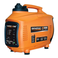
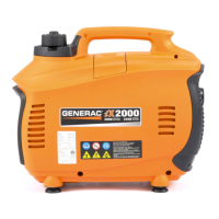
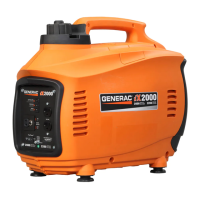
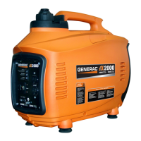
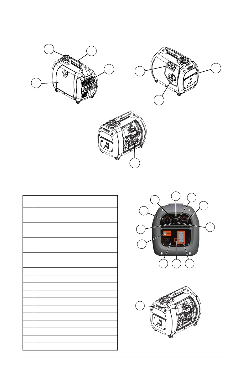
Figure 2-1. Features and Controls
TABLE 1. Generator Components
Figure 2-2. Control Panel
Figure 2-3. Data Label Location
000662
000579
1 Parallel Ready 120 Volts AC Duplex
Outlet
2 Turbo/Standard/Economy Switch
3PowerBar
4 Grounding Location
5 Reset Button
6 Overheat LED (red)
7 Overload LED (red)
8 Low Oil LED (orange)
9 Ready to Load LED (green)
10 Fuel Gauge
11 Run Time Display
12 Muffler/Spark Arrestor
13 Fuel Cap (with vent)
14 Recoil Handle
15 Carrying Handle
16 Power Dial
17 Service Door
18 Air Intake
19 Data Label Location
20 Oil Fill
003039