6 Owner’s Manual for Portable Generator
Connection Plugs
120 VAC, Duplex Receptacle
The 120 Volt outlet is overload protected by
the inverter module electronic control. See
Figure 2-4. Each receptacle will power 120
Volt AC, single phase, 60 Hz electrical loads
requiring up to 1600 watts (1.6 kW).
Figure 2-4. 120 VAC, Duplex Receptacle
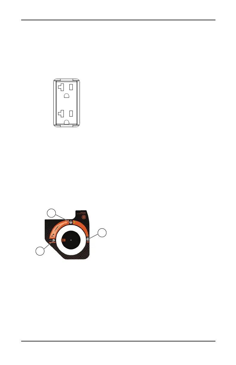
PowerDial
The PowerDial controls the ON/OFF func-
tions, choke and fuel valve operation. See Fig-
ure 2-5.
• The START position (1) is used to start the
engine. In this position, the fuel is on and
the choke is fully on (closed).
• The RUN position (2) for normal operation
and to gradually reduce the use of the
choke.
• The STOP position (3) stops the engine
and shuts off fuel flow.
Figure 2-5. PowerDial (example)
PowerBar
See Figure 2-6. The PowerBar (8) indicates
the amount of power being used from the gen-
erator. Each section is approximately 12.5%.
Economy Switch
The economy switch has 3 modes of opera-
tion:
• Economy: The quietest mode and best
when running appliances or equipment that
are resistive loads (non-motor starting),
(example: TV, video game, light, radio).
• Standard: Best when running a both induc-
tive (motor-starting loads) and resistive
(non-motor starting loads), especially when
these loads are turning on and off (exam-
ple: RV, air conditioner, hairdryer).
• Turbo: Best when running inductive loads
(appliances or equipment with motor-start-
ing) that are continually running (examples:
drill, blender, saw).
Generator Status Lights
See Figure 2-6.
• Overheat LED (red): Illuminates when unit
temperatures exceed normal operating
conditions (1). The ready LED will turn off
and the inverter will cut power to the out-
lets. Check for airflow obstructions at front
and rear panels. The engine will remain
running to cool the unit with the overheat
LED illuminated. Once the unit has reached
normal operating temperatures, the over-
heat LED will turn off. The reset button
must then be pressed for 1 second and
released to clear the fault and restore out-
put power.
• Low Oil Level LED (orange): Illuminates
when oil level is below safe operating level.
Engine shuts down (2).
• Ready LED (green): Indicates output from
generator (3) (unless there is a low oil or
overload condition).
• Overload LED (red): Indicates system
overload (4). During motor starting it is nor-
mal for the overload LED to illuminate for a
few seconds. If LED stays illuminated and
the ready LED turns off, the engine will con-
tinue to run without output power. Remove
all applied loads and determine if attached
devices exceed recommended output
power. Review for any faulty or shorted
connections. Press and hold the reset but-
ton for 3 seconds and release. The red
overload LED should turnoff. Loads can be
re-applied once the green ready LED illumi-
nates. If the red LED returns, contact an
IASD.
Run Time Display
See Figure 2-6. At startup the Run Time Dis-
play (7) shows the total engine hours of the
unit, then transitions to show the Run Time
Remaining.