Owner’s Manual for Mobile Light Tower 11
General Information
Control Panel
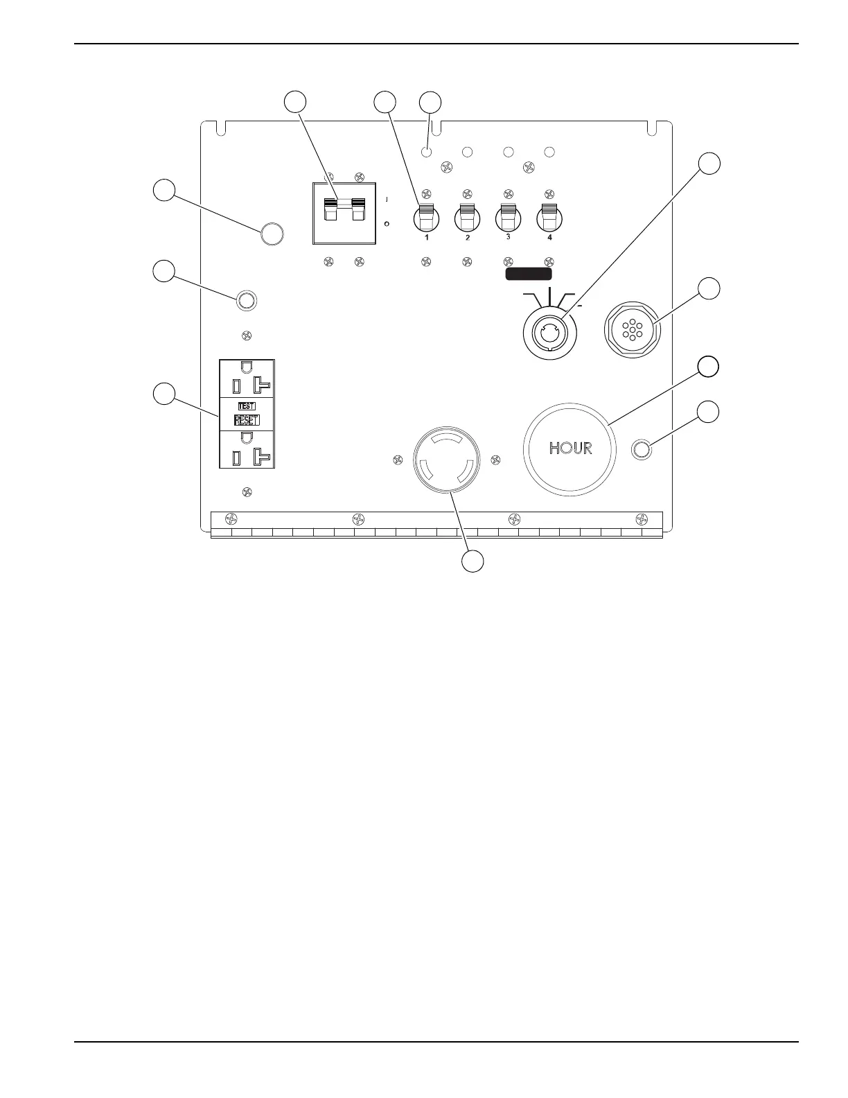
Figure 2-4. Control Panel
(A) Main Circuit Breaker
This 240V (40A) breaker will disconnect power to the
lights and auxiliary outlets. It also disables the starting
circuit if engine starting is attempted when the main
breaker is on.
(B) Light Switche (4 Locations)
One circuit breaker is supplied for each light.
(C) Ballast Indicator Light (4 Locations)
Indicates power from the ballast to each light
.
(D) Engine Starting Switch
Keyed switch operates glow plugs, starts and stops
engine.
(E) Glow Plug Indicator
Indicates operation of the engine glow plugs (Mitsubishi
engines only).
(F) Engine Hour Meter
Keeps track of engine hours for service.
(G) DC Circuit Breaker
Circuit breaker (10A) for the engine electrical system.
(H) 240V Twist-Lock Outlet
This 240V (30A) outlet supplies power for accessories
connected to the generator when the engine is running
and the main circuit breaker is switched ON (I).
(I) 120V GFCI Outlets
This 120V (20A) GFCI outlet supplies power for
accessories connected to the generator when the engine
is running and the main circuit breaker is switched ON (I).
(J) 120V Breaker
This 120V (20A) circuit breaker is supplied for the 120V
GFCI duplex outlets.
(K) 120V Breaker
This light indicates that the main circuit breaker must be
opened (switched off) before starting the engine.
400W 400W
Flagger Station Switches
120V
240V
DC
BREAKER
TURN
MAIN
BREAKER
OFF
120V
BREAKER
MAIN
BREAKER
240V
BALLAST INDICATOR LIGHTS
MAST LIGHT SWITCHES
I
O
I
O
I
O
I
O
NEUTRAL BONDED TO FRAME
ON
ON
ON ON ON ON
GLOW PLUG
INDICATOR
OFF
RUN
START
GLOW
PLUG