Generac
®
Power Systems, Inc. 9
Section 3 — Operation
PM-GC
3.3.3 ANALOG DIAGNOSTICS
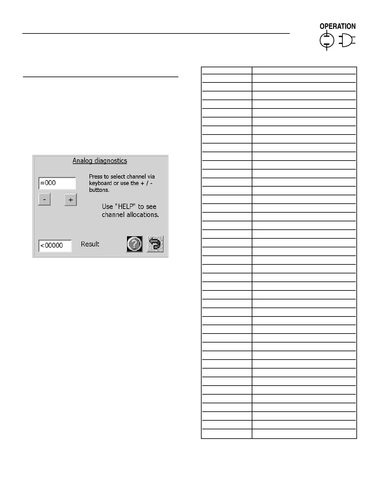
By selecting the analog submenu, the sensors con-
nected to each of the analog channels can be interro-
gated (Figure 9). The reading displayed is "raw" un-
processed data and is a decimal number ranging
from 0 - 1023 representing a voltage on the input
channel of the 10 bit ADC. Some channels have dif-
ferent scaling associated with them in hardware. The
channels are numbered and scaled as shown below:
Figure 9 — Analog Diagnostics Menu
Use the analog help button (or GenLink) to show
which user configurable channels are connected to
which sensors.
CHANNEL FUNCTION
1 Utility current sense A
2 Utility current sense B
3 Utility current sense C
4 Generator current sense A
5 Generator current sense B
6 Generator current sense C
7 Utility voltage sense A
8 Utility voltage sense B
9 Utility voltage sense C
10 Generator voltage sense A
11 Generator voltage sense B
12 Generator voltage sense C
13 4 - 20ma User config. channel 1
14 4 - 20ma User config. channel 2
15 4 - 20ma User config. channel 3
16 4 - 20ma User config. channel 4
17 4 - 20ma User config. channel 5
18 4 - 20ma User config. channel 6
19 4 - 20ma User config. channel 7
20 4 - 20ma User config. channel 8
21 4 - 20ma User config. channel 9
22 4 - 20ma User config. channel 10
23 4 - 20ma User config. channel 11
24 4 - 20ma User config. channel 12
25 4 - 20ma User config. channel 13
26 4 - 20ma User config. channel 14
27 4 - 20ma User config. channel 15
28 4 - 20ma User config. channel 16
29 4 - 20ma User config. channel 17
30 BATTERY GROUND
31 BATTERY +
32 Internal +12 VDC supply
33 Internal +5VDC supply
34 Internal -12VDC supply
35 Internal +24VDC supply
36 Internal +2.6VDC supply
37 Internal +10VDC supply
38 -
39 GROUND
40 GROUND
41 VDC reference low
42 VDC reference High

 Loading...


