Generac
®
Power Systems, Inc. 15
Section 3 — Operation
PM-GC
Critical Low Fuel level (%) Warning Alarm Units Disabled unless probe fitted
Setpoint %
Shutdown N
Dialout N
Common alarm N
Alarm log N
Sensor failure detection N
Shutdown on sensor failure N
Delay 2 seconds seconds
Active Always
Hysteresis 2 %
3.9 RUNNING HOURS
The PM-GC keeps track of how many hours the
engine has been running. This is displayed in hours
and tenths of hours. Any run of less than six minutes
duration will not be recorded. This parameter is for
display only.
3.10 EXERCISE
The generator should be programmed to exercise via
the remote start contact or, the PLC function.
3.11 SERIAL COMMUNICATIONS
The control panel has two RS232 and two RS485
communication ports. In the MPS system, one RS485
port is used to communicate to the PowerManager.
For a PM-GC controller, the ports are normally con-
figured as follows:
**1 x RS485 — Spare - can be connected to remote
annunciator(s) or relay panel(s).
1 x RS485 — Touchscreen display
1 x RS232 — GenLink® (modbus slave)
*1 x RS232 — Deep diagnostics
* This port can be reconfigured to be a modbus slave
if required. An external RS232/485 converter is
available.
**This port can be configured as a modbus slave
RS485 port for connection to external devices.
Multiple annunciators can be connected to the same
port, but they will all annunciate the same thing -
either communal results or individual results.
Apart from the display port, communications are
done via Modbus RTU protocol.
3.11.1 GENLINK
®
The control panel can communicate with GenLink®
which is a PC based program allowing both the inter-
rogation of the generator and remote programming of
its parameters. The user will be able to start and stop
the generator if it is in AUTO mode. GenLink®
communications will normally be via the GenLink®
connection port situated on the relay box. The ver-
sion of Genlink that works with PM-GC systems is
not the same as older versions of Genlink, It is called
“GENLINK - DCP”.
3.12 ADDITIONAL PANEL
COMPONENTS
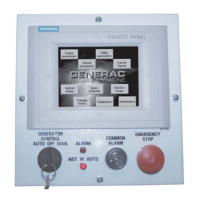
In addition to the control module, the PM-GC con-
tains the following components (see Figure 9):
3.12.1 ALARM HORN
This horn sounds an audible warning when an alarm
condition exists. See the "Alarms" section for further
information.
3.12.2 EMERGENCY STOP SWITCH
When pressed, this switch will automatically shut
down the entire generator set. The operator must
twist the switch to pop out to its original position to
reset it and allow for generator operation.
3.12.3 RELAY/FUSE BOX
The relay box houses all slave relays for engine com-
ponents (for example, starter relay, run relay, pre-
heat relay, etc.). The DC panel fuses are also mount-
ed inside this box.
3.12.4 VOLTAGE SENSING MODULE
This circuit monitors the three-phase alternator out-
put voltages. These high voltages (480, 208 etc.) at
the input to the circuits, are electronically condi-
tioned to produce low voltage outputs (typically 5v
rms) which are proportional to the alternator and
bus voltages. The outputs are used by the PM-GC
control module to determine the phase and ampli-
tude of the source.

 Loading...