Electrical Connections
26 Installation Guidelines for 50 Hz PowerPact™
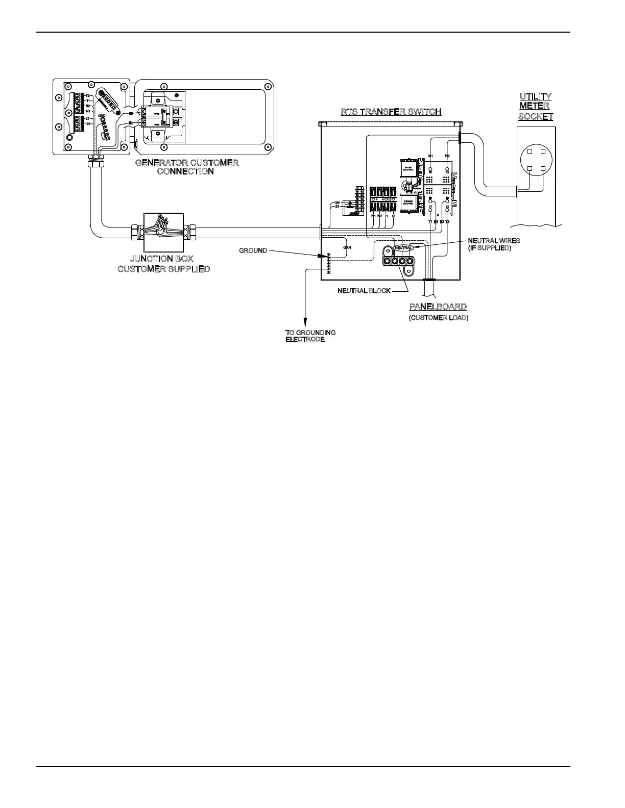
Main AC Wiring
Figure 6-2. Main AC Wiring
NOTE: Main AC wiring must be in accordance with local
jurisdiction and codes.
1. Strip the insulation off the wire ends. Do not
remove excessive insulation.
2. Open the controller access panel and latch it.
Loosen the lugs of the Main Breaker through the
access holes.
3. Insert a power wire (E1 or E2) into the bottom lug
of the Main Breaker. Torque to the proper
specification.
4. C
onnect the Neutral wire to the Neutral bar and
torque to the required specification. Se
e
Figure 6-2
.
5.
Connect the Ground wire to the Ground bar and
torque to the required specification. Se
e
Figure 6-2
.
6. Plug the breaker access hole with the cap plugs
provided (see Parts Shipped Loose).
7. Unlatch the controller access panel by pulling
towards you and then close the lid.
8. Confirm the integrity of the ground wire connection
between the electrical access panel and the
ground lug while closing the customer connection
box using the two short Allen screws.
NOTE: Neutral Bonding - For installations that require
the neutral to be bonded to the ground, this is to be done
on the customer connections terminals inside the
generator. Connect a suitably sized wire from the neutral
bar to the ground bar. This is normally required when the
generator is the source in a separately derived system. It
is not required when the generator is a backup source in
a utility supplied electrical system with a 2-pole transfer
switch. See Figure 6-1.
NOTE: Torque all wiring lugs, bus bars and connection
points to the proper torque specifications. Torque
specifications for the Main Line Circuit Breaker (MLCB)
can be found on a decal located on the inside of the
electrical access panel.
001130
RTS TRANSFER SWITCH
23
TO GROUNDING
ELECTRODE
NEUTRAL BLOCK
PANELBOARD
NOTE WIRE ORIENTATION
WARNING
TRANSFER
+12VDC
194
(CUSTOMER LOAD)
SOCKET
UTILITY
METER
T1
N2
N1
23
194
E2
E1
GND
GENERATOR CUSTOMER
CONNECTION
CUSTOMER SUPPLIED
JUNCTION BOX
UTILITY
STANDBY
(C1 & VR1)
(C2 & VR2)
23
T1N1 N2 T2
194
T1
T1
E2
E1
T2
T2
E1
N1
E2
N2
N1
N2
GROUND
GRN NEUTRAL
NEUTRAL WIRES
(IF SUPPLIED)
T2
 Loading...