Do you have a question about the Generac Power Systems PowerPact G0065201 and is the answer not in the manual?
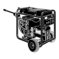
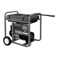
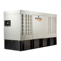
Overview of the compact, high-performance, air-cooled, engine-driven generator for critical loads.
Alerts personnel to special instructions about hazardous operations, defined as DANGER, WARNING, and CAUTION.
Overview of the compact, high-performance, air-cooled, engine-driven generator for critical loads.
Important guidelines and precautions for safe installation, operation, and maintenance of the generator.
Guidance on contacting an Independent Authorized Service Dealer for assistance and locating a dealer.
Precautions regarding jewelry, clothing, hair, and appendages near moving parts for safety.
Caution against touching hot surfaces and keeping the machine away from combustibles.
Warning against altering construction or blocking ventilation, which can cause unsafe operation or damage.
Warning against using the generator as a step, which can lead to injury or damage.
Requirement for qualified personnel for installation, operation, and maintenance to prevent injury and damage.
Danger of asphyxiation from carbon monoxide, requiring indoor CO alarms and adequate ventilation.
Warning about electrocution risk from contact with bare wires, terminals, and connections while the generator is running.
Mandate for licensed electrician to install transfer switch to prevent electrocution and death.
Warning about death, serious injury, and equipment damage from electrical backfeed without proper switchgear.
Importance of verifying proper grounding before applying power to prevent electrocution.
Fire hazard from obstructing cooling and ventilating airflow, leading to potential fire or damage.
Requirement for compliance with codes for fire and explosion prevention during installation.
Recommendation to use only fully-charged fire extinguishers rated for electrical fires.
Mandatory compliance with applicable codes, standards, laws, and regulations for installation.
Use of approved switchgear to isolate generator to prevent backfeed and ensure safety.
Emphasis on qualified service personnel for installation and operation to prevent injury and warranty voidance.
Warning about explosion and fire risk from flammable fuel and vapors; prohibition of fuel leakage.
Requirement for qualified technician for fuel source connection to prevent injury and damage.
Caution to allow fuel spills to dry completely before starting the engine to prevent fire risk.
Risk of fire from hot surfaces igniting combustibles, leading to severe injury or death.
Contacting local authorities for permits and inspections before starting the installation.
Thoroughly reading and understanding all manual sections and contacting support if unclear.
Full compliance with NEC, NFPA, OSHA, and local codes for generator installation.
Verifying the capacity of the natural gas meter or LP tank for sufficient fuel supply.
Information on local code requirements for AFCIs and compatible transfer switch panels.
List of applicable NFPA and building codes for generator installation, with sources.
Guidelines for inspecting the unit for damage upon delivery and filing claims promptly.
List of essential tools needed for unpacking, installation, and maintenance of the generator.
Detailed steps for removing the generator from its packaging and performing a visual inspection for damage.
List of parts shipped loose with the generator, including their location and identification.
Recommendations for generator placement, clearance, and environmental considerations for safe operation.
Specific clearance requirements from structures, openings, and vegetation for airflow and maintenance.
Guidelines for selecting base material (gravel or concrete) and ensuring the generator is level.
Requirements from NFPA 37 for outdoor engine installation, including minimum separation distances.
Information about the SwRI decal and its significance regarding fire safety testing.
Tips for choosing a site that provides adequate airflow and avoids obstruction by debris or fumes.
Detailed instructions for preparing a compacted gravel pad or a concrete pad for generator installation.
Specifications for digging and filling a gravel pad to ensure a level installation base.
Instructions on how to safely move the generator using a hand cart or rails, with precautions against damage.
Information on the purpose and mandatory use of composite pads for elevating and protecting the generator.
Instructions for securing the generator to a concrete pad using lag bolts, emphasizing not removing the pads.
Guidelines for fuel types (NG/LP), BTU content, and pressure, with safety warnings.
Step-by-step instructions for converting the generator from natural gas to liquid propane fuel.
Table showing fuel consumption rates for natural gas and LP vapor at different load levels.
Chart for determining the correct pipe size based on kVA rating and maximum length for natural gas.
Chart for determining the correct pipe size based on kVA rating and maximum length for LP vapor.
Emphasis on correct gas pipe sizing for proper generator operation and 125% load rating.
Adherence to safety procedures, codes, and regulations for combustible gas line connections.
Mandatory installation of an accessible manual full flow shut-off valve on the fuel line.
Guidelines for using UL Listed/AGA-approved flexible fuel lines to isolate vibration and prevent leaks.
Recommendation to install a sediment trap as required by local codes.
Procedure for checking gas connections for leaks using non-corrosive leak detection fluid.
Steps for checking gas pressure at the regulator using a manometer, referencing fuel requirements.
Labels and descriptions for components in a typical natural gas vapor installation diagram.
Labels and descriptions for components in a typical LP vapor installation diagram.
Guidelines for control wire length, size, and connection points to the generator control panel.
Table detailing terminal numbering decals and corresponding wire numbers for control panel connections.
Instructions for installing conduit and routing wires through a NEMA 3 rated external connection box.
Diagram illustrating the main AC wiring connections between the generator, transfer switch, and panelboard.
Step-by-step instructions for connecting the main AC wiring, including torque specifications.
Explanation of neutral bonding requirements for separately derived systems versus utility-supplied systems.
Details on the required battery type, voltage, and CCA rating for the generator.
Warnings regarding battery explosion, acid burns, and electrical shock hazards during installation.
Step-by-step instructions for correctly connecting the positive and negative battery cables.
Procedure for installing the battery bracket to secure the battery.
Description of the Auto/Off/Manual interface, including alarm LEDs, warning LEDs, and mode buttons.
Explanation of the AUTO, MANUAL, and OFF buttons and their functions for generator operation.
Essential steps to complete before the initial start-up, including checking generator status and fuel supply.
Guidelines for selecting the appropriate engine oil viscosity based on operating temperature.
Explanation of the generator's exercise timer and how to set or change the weekly exercise time.
Warning against manual transfer under load, emphasizing disconnecting power sources first.
Steps to verify utility power voltage and compatibility before connecting the generator.
Procedure for checking generator AC output voltage and frequency under no-load and load conditions.
Steps for testing the generator at full rated load for 20-30 minutes, checking for abnormalities.
Procedure for verifying the generator's automatic start-up and transfer to standby during utility failure.
Steps for verifying proper installation, testing operation, and educating the end user.
Instructions for safely turning the generator off while it is running under load for maintenance or fuel conservation.
A table listing common problems, their causes, and recommended solutions for generator operation.
Troubleshooting steps for when the engine fails to crank, covering fuse, battery, and starter issues.
Troubleshooting steps for when the engine cranks but does not start, including fuel and spark issues.
Troubleshooting steps for an engine that starts hard or runs rough, addressing air cleaner, spark plugs, and fuel pressure.
Troubleshooting steps for when there is no AC output from the generator, checking the circuit breaker and internal failure.
Troubleshooting steps for when the generator fails to transfer to standby power after utility failure.
Troubleshooting steps for excessive oil consumption, including checking oil level and seals.
A table for diagnosing system issues based on active alarms, LED indicators, problems, and checks.
Troubleshooting steps for high temperature shutdown, focusing on ventilation and contacting service.
Troubleshooting steps for low oil pressure issues, including checking oil level and contacting service.
Troubleshooting steps for overcrank faults, checking fuel shutoff and starting in manual mode.
Troubleshooting steps for battery problems, checking the battery menu and contacting service.
Instructions for performing break-in maintenance and clearing the 'Maintenance Due' light.
Instructions for performing scheduled maintenance and clearing the 'Maintenance Due' light.
Troubleshooting for flashing active mode LEDs when utility is present, checking utility sense lines.
Description of accessories available for air-cooled generators, including their purpose and benefits.
Recommendation for the Cold Weather Kit in areas with temperatures below 32°F (0°C).
Information on the Scheduled Maintenance Kit for performing generator maintenance.
Description of the Wireless Local Monitor for instant status updates and alerts.
Illustrations showing the left side and front views of the generator with key dimensions.
Illustrations showing the right side and rear views of the generator with inlet/outlet and fuel connection details.
Diagram detailing the electrical connections between the generator components, AVR, controller, and wiring legend.
Diagram illustrating dead front plate connections, generator output, utility sense, and AC load supply.
Schematic diagram showing stator, rotor, controller, and battery connections with a detailed legend.
Diagram showing AVR and controller inputs and outputs, including utility and load supply connections.
| Brand | Generac Power Systems |
|---|---|
| Model | PowerPact G0065201 |
| Category | Portable Generator |
| Language | English |