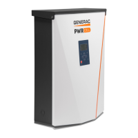
8 Owner’s Manual for Generac PWRcell Inverter
General Information
Internet LED
Internet LED (G) is illuminated when the inverter is
connected to a router and has an IP address. See
Ethernet Configuration.
NOTE: A blue Internet LED does not mean that the
inverter has a connection to with the Generac server.
Shutdown Mode
NOTE: A loss of grid power will not de-energize REbus
in a PWRcell system configured to island with enabled
energy storage.
Shutdown button (E) activates a transition to shutdown
system mode. Use of the shutdown system mode is only
intended for servicing and troubleshooting equipment. It
is not intended to be utilized to meet NEC rapid shutdown
requirements.
Shutdown mode signals all communicating PWRcell
equipment on REbus, including the PWRcell inverter, to
disable. Disabled PWRcell equipment will drop their
output voltages to safe levels.
To enter shutdown, press and hold shutdown button (E).
In shutdown mode:
• PWRcell inverter will stop sourcing power to
REbus, and immediately disable all communicating
power sources on REbus by sending a system-
wide system mode change signal.
NOTE: Successful signal transmission relies upon
proper configuration of PLM channels across REbus
devices (PV Links and Batteries).
• Shutdown LED (F) will illuminate.
• Disabled PWRcell batteries will open their REbus
contacts.
• Inverter screen (A) will display REbus DC bus volt-
age and text indicting shutdown mode has been
initiated.
NOTE: The AC section of the inverter will still be
energized unless the building AC disconnect or main
service breaker is shut off.
System Modes Overview
Generac PWRcell offers several system modes for various installation configurations, markets, and applications.
Connected REbus devices work together to manage the distribution of power based on the selected system mode.
Some modes interact with PWRcell batteries to store power and/or balance production and consumption.
See Table 2-1 and Table 2-2 for an overview of available system modes.
Grid Tie
In Grid Tie mode, the PWRcell inverter functions as a
conventional grid-tied inverter system. The system
powers local loads and when generation exceeds load
demand, excess power is exported to the utility for net
metering and other credits.
NOTE: Grid Tie is intended for use with systems that do
not include a PWRcell battery. For systems where a
PWRcell battery will be connected at a later date, operate
in Grid Tie mode until the battery is installed.
(000600)
DANGER
Electrocution. Initiate a system-wide shutdown and turn the
PWRcell DC Disconnect Switch OFF on all connected
batteries before performing service. Failure to do so will
result in death, serious injury, or equipment and property
damage.
Table 2-1. Most Common System Inverter Modes
Priority Grid Tie Clean Backup Priority Backup Self Supply
1 Support local loads Charge batteries from bus Charge batteries from bus Support local loads
2 Export to grid Support local loads Charge batteries from grid Charge batteries from bus
3 - Export to grid Support local loads Export to grid
4 - - Export to grid -
Table 2-2. Optimal Configuration for Goal
Goal Optimal Inverter Configuration
Keep batteries charged as much as possible Priority Backup
Keep batteries charged using only solar power Clean Backup
Net-metering solar energy without a battery Grid Tie
Use grid as little as possible Self Supply
 Loading...