11
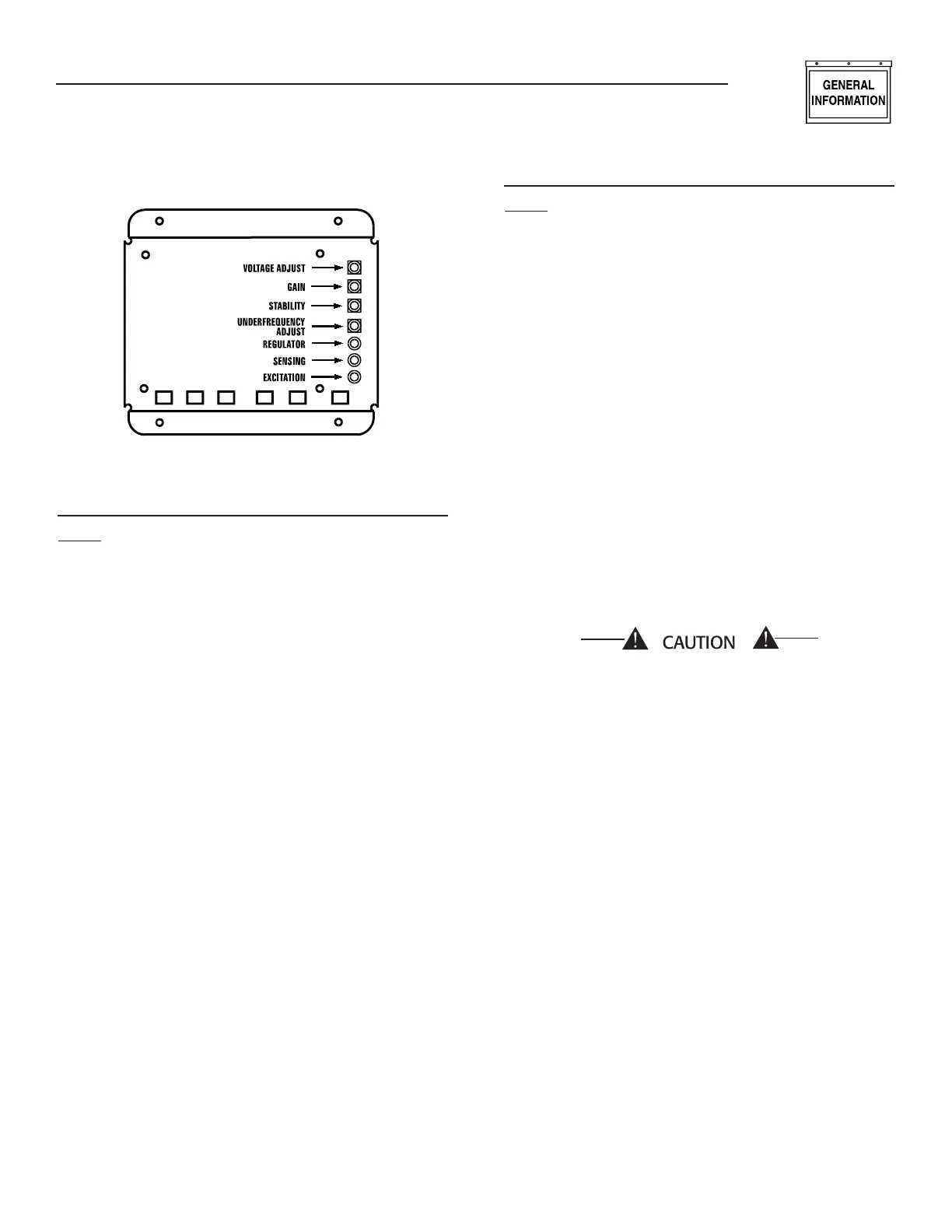
Figure 4 — Voltage Regulator
R-200 J1 CONNECTOR (23 PIN,
GRAY=1800RPM, WHITE=3600RPM)
Pin #
1 Governor 12V Supply
2 Reserved (Do not connect any wires to this
pin.)
3 GND-B to Governor Driver
4 Hi-Coolant Temp Input
5 0V to Governor Driver
6 5V Supply to Governor Driver
7 Distributor (Hall Sensor) 12V Sensor Supply
8 Low Coolant Level Input
9 3.0L Crank Signal Input
10 3.0L Crank Signal Return
11 Low Fuel Pressure Input
12 Governor Position Feedback Input
13 Reserved (Do not connect any wires to this
pin.)
14 Coil + (Supply voltage to engine coil pack.)
15 Coil A Driver
16 2.4L Distributor Sensor Return
17 2.4L Distributor Sensor Input
18 Governor PWM Output
19 Governor Enable Output
20 Lo Oil Pressure Input
21 2.4L Flywheel Sensor Screen or 3.0L Crank
Sensor Screen
22 Coil C Driver
23 Coil B Driver
R-200 J2 CONNECTOR (14 PIN WHITE)
Pin #
1 Reserved (Do not connect any wires to this
pin.)
2 Start (Crank) Relay Driver Output (minimum
coil resistance is 90 ohms)
3 Fuel (Run) Relay Driver Output (minimum
coil resistance is 90 ohms)
4 2-wire Start Input (from relay contact in W-
type transfer switch)
5 Momentary Open Switch Input (B+)
6 2-wire Start Return (from relay contact in W-
type transfer switch)
7 Manual/Auto Input (+BS)
8 19.5VAC Utility Sense Input
9 Alarm Relay Driver Output (minimum coil
resistance is 90 ohms)
10 Transfer Relay Driver Output (minimum coil
resistance is 60 ohms)
11 Manual Input
12 19.5VAC Utility Sense Return
13 Reserved (Do not connect any wires to this
pin.)
14 GND-B (Battery Ground)
Refer to the individual generator wiring dia-
grams and schematics for additional informa-
tion.
2A AND 10A BATTERY CHARGERS
There are two types of battery chargers. A 2 Amp bat-
tery charger and a 10 Amp battery charger.
The 2 Amp battery charger is a "float" type charger. A
"float" type charger will charge the battery at its maxi-
mum output current rating until the battery voltage
reaches a "float" voltage and then the charge current
will decrease to maintain the battery at that "float"
voltage.
The 10 Amp battery charger is an "equalize" type
charger. An "equalize" type charger will charge the
battery at its maximum output current rating until
the battery voltage reaches an "equalize" voltage and
then the charge current will decrease to maintain the
battery at a lower "float" voltage.
General Information
R-panel Technical Manual
 Loading...


