EasyManua.ls Logo

General Monitors TA402A User Manual

Default Icon
51 pages
To Next Page IconTo Next Page
Page #1 background imageLoading...
Page #1 background image
The information and technical data disclosed in this
document may be used and disseminated only for the
purposes and to the extent sp ecifically authorized in writing
by General Monitors.
Instruction Manual 11/03
General Monitors reserves the right to change published
specifications and designs without prior notice.
Part No MANTA402A
Revision E/11-03
ModelTA402A
Zero Two Series Trip Amplifier
Module for Flame Detection
Applications

Table of Contents

Question and Answer IconNeed help?

Do you have a question about the General Monitors TA402A and is the answer not in the manual?

General Monitors TA402A Specifications

General IconGeneral
Signal Output4-20 mA
Output Current4-20 mA
Input Voltage24 VDC
Input Voltage Range18 to 32 VDC
Protection RatingIP66

Summary

Warranty and Warnings

Warranty Statement

Product warranty terms, duration, and coverage details.

Safety and Operational Warnings

Critical safety and operational warnings for product use and installation.

Introduction to TA402A

Features and Benefits

Key features and advantages of the TA402A module.

TA402A Specifications

System Specifications

Details application, detector types, response times, indicators, modes, approvals, warranty.

Engineering Specifications

System requirements and TA402A module capabilities for engineers.

Installation Guide

Rear Terminal Connections

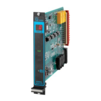
Wiring instructions for the TA402A's rear terminal block.

A2 Time Delayed Alarm Outputs

Terminal designations and relay states for A2 time-delayed alarms.

A1 Immediate Warn Outputs

Terminal designations and relay states for A1 immediate warnings.

Flame Detector Connections

Terminal designations for connecting the flame detector.

Detector Location Considerations

Guidelines for optimal flame detector placement.

Operation and Maintenance

Electrical Outputs

Lists and rates relay contacts and open collector outputs.

Accepting Alarm Conditions

Acknowledging new alarms using the Master Accept Button.

Resetting Latched Alarms

Manual reset for latched alarms and LED Test function.

Card Test Feature Functionality

How to perform a functional test of module alarm circuits.

Fault Diagnostics and Codes

Summarizes fault codes and troubleshooting steps.

User Interfaces

Setup Check and Setup Modes

Viewing and changing module parameters via Setup modes.

Entering Setup and Password Modes

Accessing Setup modes and entering the password.

Entering Inhibit Mode

Activating and exiting Inhibit Mode for alarm suppression.

Appendix C: Ordering Information

Product Ordering Information

Model number configuration and options for ordering the TA402A.

Related product manuals