English
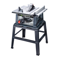
10" Table Saw
Operator’s Manual GTS10SB
16
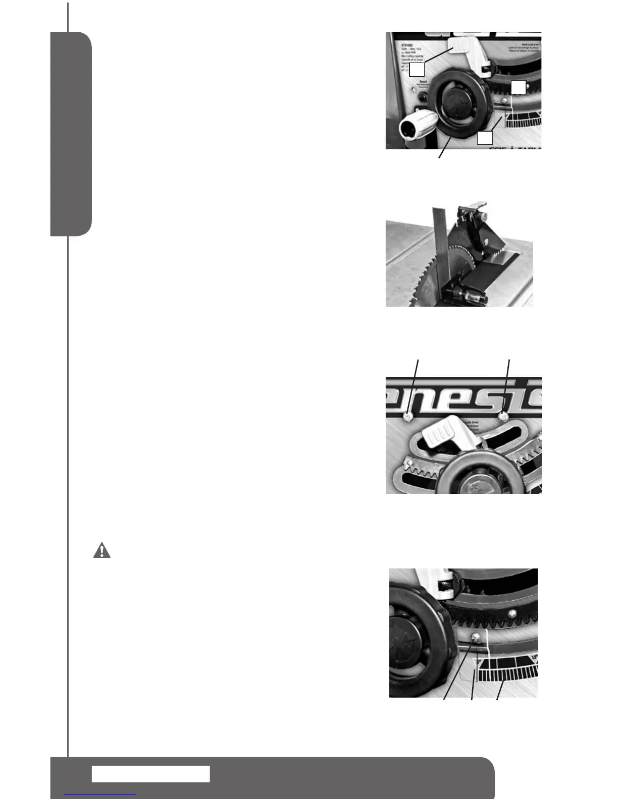
BLADE HEIGHT ADJUSTMENT (FIG 14)
1.Turnthebladecontrolwheel(1).Turningitclockwiselowers
theblade.Turningitcounterclockwiseelevatesit.
2.Forthroughcuts,placetheworkpiecetobecutushagainst
blade,andsetthebladesothattipsonthetopofbladeare
about1/8”(3mm)higherthantheworkpieceandthevalley
betweentheteethislowerthantheworkpiece.
3.Fornon-throughcuts,usearulertomeasurefromthetable
surfacetothetipoftheuppermosttoothontheblade.
90° AND 45° POSITIVE STOPS ADJUSTMENT
(FIG 14, 15, 16)
Thesawhaspositivestopsthatwillquicklypositionthesaw
bladeat90°or45°tothetable.Makethefollowingadjustments
onlywhenitisneeded.
To Adjust 90° Positive Stop
1.Removethebladeguard.
2.Raisethebladetothehighestpossiblepositionbyturning
bladecontrolwheel(1)counterclockwise.
3.Loosenthebevellockinglever(2).Pushthebladecontrol
wheel(1)andturnclockwiseasfaraspossible.
4.Place acombinationsquare ushonthetableand ush
againstthebladetodetermineifthebladeisata90°angle
tothetable.SeeFIG15.
5.Ifthebladeisnotata90°angletothetable.Loosenthe
screw(7).Adjustthebevelsothatthebladeisata90°
angle.Lockthebevellockinglever(2).
6.Turnthe90°jamnutconnectingwithscrew(7)frominside
ofthebasetomakesurethereisnomovement.Tightenthe
screw(7)tosecure.
To Adjust the 45° Positive Stop, follow the same
procedures as adjusting the 90 positive stop. Set
the blade at a 45° angle against a combination
square. The 45° positive stop adjusting screw
and jam nut (8) is on the right side. See FIG 16.
WARNING: To prevent personal Injury,
always unplug the saw from the power source
before make any adjustments.
BLADE BEVEL INDICATOR ADJUSTMENTS
(FIG 15, 17)
1.Loosenbevellockinglever(2),pushbladecontrolwheel(1)
andturnclockwisetopositionthebladeat90°measuredby
usingcombinationsquare.(SeeFIG15)
2.Loosentheholdingscrew(4),positionthepointer(4)over0°
andtightenthescrew(4).
NOTE: Always make a trial cut on a piece of
wood when make critical cuts. Measure the cut
accuracy.
FIG 15
4
3 5
FIG 17
FIG 14
1
2
3
6
FIG 16
7 8
 Loading...