15
English
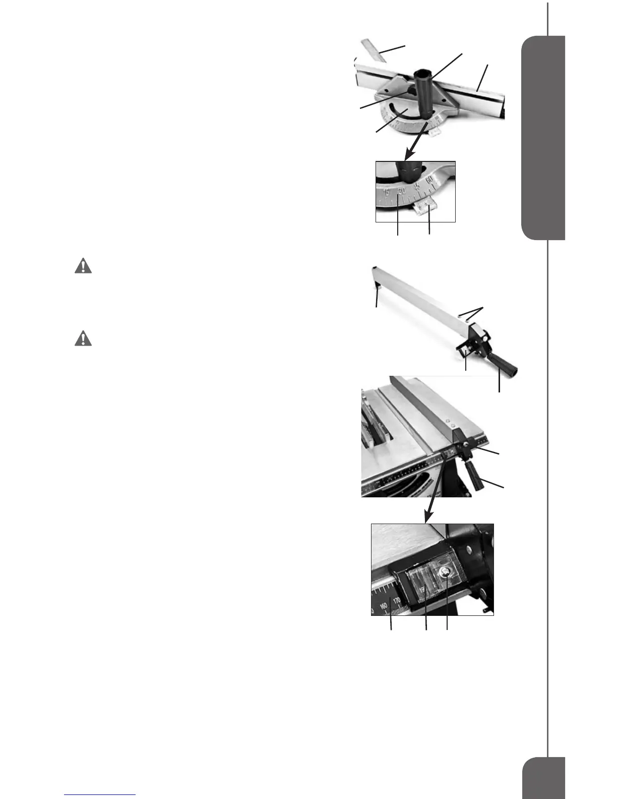
NOTE:Themitergaugebody(2)hasmarksat5degrees
increments. The sliding bar (3) has marks at 1 degree
increments.Readbothtogetanaccurateangledegree.
To adjust the Miter Gauge Fence,loosenthelock
knob(4)andslidethefence(5)tothedesiredposition.Then
tightenthelockknob(4).(SeeFIG12)
RIP FENCE INSTALLATION (FIG 13)
Theripfenceispre-assembledatthefactory.Toinstallthe
RipFence,placetheendfurthest(2)fromthelockhandle(1)
sothatangeisovertherearedgeofthetable,thenlower
theendclosest to the handleoverthe front rail.When the
Lockdownhandle(1)isintheUPposition,theangesare
relaxed,allowingyoutore-positiontheRipFence.Whenthe
LockdownhandleisintheDOWNposition,theangesare
lockedwithrailsinplace.(SeeFIG13)
WARNING:The Rip Fence must be
parallel with the Saw Blade in order to prevent
Kickback when rip cutting.
RIP FENCE ADJUSTMENT (FIG 13)
WARNING: To prevent personal Injury,
always unplug the saw from power source
before make any adjustments.
To adjust the Rip Fence,liftthelockhandle(1)totheUP
position.Useindicator(3)onthefencetoslidetheRipFence
todesiredposition.MakesurethefrontbarontheRipFence
isushagainstfrontrail.ThenlockDOWNthelockhandle.
To adjust the tension on the Rip Fence,youmay
turnthetension adjustmentknob(4) clockwisetoincrease
thetensionorturncounterclockwisetodecreasethetension.
To align Rip Fence,pleasefollowthestepsbelow:
1.Liftthelockhandle(1)toUPposition.
2.SlidetheRipFencebythehandleuntilitisalongsidethe
sawblade.Thefenceshouldtouchthe“SET”teethatthe
frontandrearoftheblade.Ifnot,continuethefollowing
thesteps.
3.Loosenthetwohexscrews(5)onthetopfrontsectionof
thefence.
4.Movethefenceuntilittouchestheteethandisparallelto
theblade.
5.Holdthefenceinplaceandlowerthelockhandle,then
tightenhexscrews.
The distance of the Rip Fence body from the blade when rip
cuttingontherightsideofthebladeisdeterminedbyaligningthe
DistanceIndicator(3)withthedesireddimensiononthescale(6).
ToadjusttheRipFenceDistanceIndicator,loosentheadjustment
screw(7),adjusttheindicator(3)andthentightenthescrew(7).
FIG 12
2
5
1
3
2
3
4
6
1
4
1
3
5
2
3 7
FIG 13
 Loading...