English
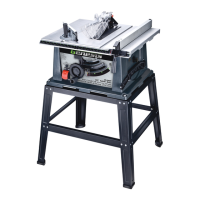
10" Table Saw
Operator’s Manual GTS10SB
14
WARNING:To prevent personal Injury,
always unplug the saw from power source
before make any adjustments.
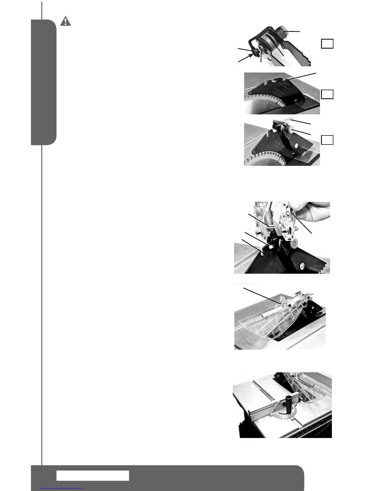
INSTALLING THE ANTI-KICKBACK PAWLS
NOTE:Thesplitter(1)needstobeinworkingpositionto
installtheanti-kickbackpawlassembly.
1.Raisethebladetothehighestpositionandsetbevelat0°.
Makesurethebevelislockedtight.
2.Placetheanti-kickbackpawlassemblyoverthe"keyhole"
slot(4)onthesplitter(1).Depresstheplasticcap(3)on
thelockpin(5)inthedirectionshownonFIG8-A,Rotate
thelever(7)downwards,andmakesurethelockpinfully
engagestheslot(4).SeeFIG8-C
4.Releasetheplasticcap(3)tosecure.SeeFIG8-C.Make
sure there is no movement of the anti-kickback pawl
assembly.
Toun-install theanti-kickbackpawlassembly.Depressthe
plasticcap(3)onthelockpin(5)torelease.Rotatethelever
(7)downwards,Pullandremovetheassemblyoffthesplitter.
INSTALLING THE BLADE GUARD (FIG 9,10)
1.Positionthebladeguardassembly(5)overthe"L"shaped
slot(3)onthesplittersothatthepin(1)engagestheslot
(3)completely.SeeFIG9.
2. Place the blade guard assembly down on the splitter.
Depressthesilverlockbutton(2).
3.Slidethebladeguardassemblybackwardsandpushit
downwardswithalittleforcesothatthelockpinengages
fullyintotheslot4.
4.Releasethesilverlockbutton(2)tosecure.SeeFIG10.
MITER GAUGE INSTALLATION (FIG 11)
Themitergaugeispre-assembledatthefactory.Toinstallit,
simplyslidemitergaugeguideintothemitergaugegrooveon
thesawtableasshowninFIG.11.
NOTE:Therearetwomitergaugegrooves,oneoneither
sideoftheblade.Whenmaking90°crosscut,youmayuse
eitherofthegrooves.Whenbevelcutting,usethegrooveon
therightsidesothatthebladeistiltedawayfromthemiter
gaugeandyourhand.
MITER GAUGE ADJUSTMENT (FIG 12)
To adjust the miter gauge angle,loosenmitergauge
lockhandle(1)androtatethemitergaugebody(2)sothat
the"0"markontheendoftheslidingbarpointstodesired
position.Thentightenthelockhandle.SeeFIG12.
5
6
4
2
1
1
6
7
3
A
B
C
FIG 8
FIG 9
FIG 10
2
1
3
4
5
FIG 11
 Loading...