Do you have a question about the Genie Z-34/22N and is the answer not in the manual?
Safety rules and operating instructions are key for maintenance.
Information accuracy and continuous improvement policy.
How to get in touch with Genie for support.
Instructions to locate manuals on the Genie website.
Warning about death or serious injury from not following safety rules.
Conditions required before performing maintenance procedures.
Awareness of hazards for personnel working on or around machines.
Awareness of hazards for personnel working in the workplace.
Details on tires, wheels, load range, dimensions, and fuel capacities.
Torque specifications for wheel lug nuts.
Capacities for hydraulic tank and system.
Weights of various machine components for different models.
Drive speed, braking distance, and boom function speeds for models.
Requirements for hydraulic oils and optional fluids.
Temperature ranges for various hydraulic fluids.
Properties of various hydraulic fluids including Chevron and Shell.
Specifications for pumps, plugs, and valve coil resistance.
Torque values for various components like rotators, bearings, hubs, brakes, and motors.
Torque specifications for Seal-Lok™ and JIC 37° fittings, and O-ring boss ports.
Procedures for torqueing Seal-Lok™ and JIC 37° fittings.
Specific configuration required for performing maintenance procedures.
General rules to follow before performing maintenance.
Chart detailing inspection frequency based on hours or time.
Inspect manuals/decals, perform pre-operation inspection and function tests.
Inspect battery, wiring, tires, brakes, drive hubs, and test self-leveling.
Grease and test the platform overload mechanism and system.
Check boom wear pads, free-wheel config, bearing bolts, drive hub oil, and filters.
Test or replace hydraulic oil and grease steer axle wheel bearings.
Steps to take before starting repair procedures, including safety.
Overview of the repair procedures section.
Explanation of symbols used in the repair procedures.
Information about drive joystick and boom function speed controller adjustments.
Function, removal, and bleeding of the platform leveling slave cylinder.
Information, removal, and bleeding of the platform rotator.
Steps to calibrate the platform overload system for safe operation.
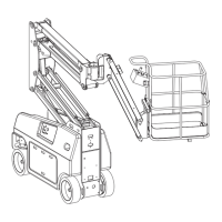
Information and steps for removing the jib boom and bell crank.
Information and steps for removing the jib boom rotator.
Information and steps for removing the jib boom lift cylinder.
Steps to repair the primary boom cable track.
Procedure for shimming and removing the primary boom.
Steps to disassemble the primary boom.
Information and steps for removing the primary boom lift cylinder.
Information and steps for removing the primary boom extension cylinder.
Information and steps for removing the platform leveling master cylinder.
Steps to disassemble the secondary boom.
Information and steps for removing the secondary boom lift cylinder.
Information and steps for removing the auxiliary or function pump.
Components of the function manifold with schematic items and torque.
Procedures for adjusting system, primary boom, and secondary boom relief valves.
Procedure to adjust the turntable rotate relief valve.
Components for jib boom/platform rotate manifold based on serial numbers.
Procedure to test valve coil resistance and diodes.
Information and steps to remove the turntable rotation hydraulic motor.
Information, removal, and installation of hub and bearings for 2WD models.
Information and procedure to test the motor controller.
Steps to take before troubleshooting fault codes, including safety.
Explanation of fault codes and their meaning indicated by controller lights.
Table listing fault codes, conditions, causes, and solutions.
Overview of the electrical and hydraulic schematics sections.
Explanation of electrical symbols used in diagrams.
Explanation of hydraulic symbols used in diagrams.
Diagram illustrating the power cable connections.
Wiring diagram for the drive contactor panel.
Wiring diagram for manifolds and limit switches.
Wiring diagram for the LVI/BCI option.
Information about the work and drive lights option.
Information about the CTE option for CE models.
Information about the charger interlock option.
Overall hydraulic schematic of the machine.
Electrical schematics for ANSI/CSA/AS and CE models across serial ranges.
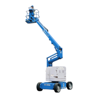
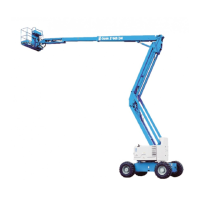
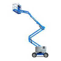
| Working Height | 12.52 m |
|---|---|
| Platform Height | 10.52 m |
| Horizontal Reach | 6.78 m |
| Lift Capacity | 227 kg |
| Platform Rotation | 180° |
| Turntable Rotation | 355° Non-Continuous |
| Power Source | 48 V DC (eight 6 V batteries) or Kubota Diesel Engine |
| Stowed Height | 2.00 m |
| Drive Speed - Raised | 1.1 km/h |
| Maximum Platform Height | 10.52 m |
| Platform Length | 0.76 m |
| Drive Speed - Stowed | 6.0 km/h |
| Tyres | Solid Rubber |
| Fuel Type | Diesel |