Do you have a question about the Genie Z-45/22 and is the answer not in the manual?
Key safety and operational information for using the Genie Z-45/22.
Warning about severe injury or death from ignoring safety rules.
Conditions required before performing maintenance on the machine.
Specifications for tires, wheels, lug nuts, and tire pressure.
Capacities for fuel, propane, and hydraulic fluid tanks.
Maximum drive speeds for 2WD and 4WD models.
Speeds for primary boom, secondary boom, and turntable functions.
Specifications for the drive pump, including displacement and pressure.
Pressure and flow regulator specifications for the drive manifold.
Torque values for SAE Grade 5 bolts.
Torque values for SAE Grade 8 bolts.
Oil pressure and capacity specifications for the lubrication system.
Recommended oil viscosity based on ambient temperature.
Recommended gap for spark plugs in inches and millimeters.
Torque sequence for cylinder head bolts.
Oil pressure and capacity specifications for the lubrication system.
Recommended oil viscosity based on ambient temperature.
Critical safety and procedural guidelines for performing inspections.
Outlines the four types of maintenance inspections: daily, quarterly, annual, and two-year.
Details daily and 100-hour scheduled maintenance procedures.
Procedure to check the condition and presence of operator and safety manuals.
Details scheduled maintenance procedures for various checks and tests.
Procedure to inspect engine belts for wear and tension.
Test procedure for the oscillate lock-out feature on equipped models.
Procedure to test the automatic platform self-leveling system.
Details scheduled maintenance procedures related to various component checks and replacements.
Procedure to inspect and adjust primary boom wear pads for proper clearance.
Details scheduled maintenance procedures for fluid and line checks and replacements.
Procedure for testing or replacing hydraulic oil and cleaning strainers.
Guidance on how to use and complete the maintenance inspection report.
List of daily inspection items.
Critical safety and procedural guidelines for performing maintenance.
Explanation of symbols used in the procedures, including danger, warning, caution, and notice.
Procedure to check the condition and presence of operator and safety manuals.
Procedure to check for damage or illegibility of safety and instructional decals.
Daily inspection for machine damage, loose or missing parts.
Critical safety and procedural guidelines for troubleshooting.
Preparatory steps and safety awareness before starting troubleshooting.
Critical safety and procedural guidelines for performing repairs.
Steps to take before beginning any repair procedure.
Explanation of symbols used in repair procedures.
Information on joystick controller operation and maintenance.
Steps for adjusting the primary boom up/down controller for proper operation.
Step-by-step guide for adjusting the horsepower limiter board.
Procedure for removing the platform from the machine.
Procedure for removing the platform leveling slave cylinder.
Procedure for removing the platform rotator assembly.
Procedure for repairing the plastic cable track on the primary boom.
Procedures for shimming primary boom wear pads.
Detailed procedure for removing the primary boom lift cylinder.
Detailed procedure for removing the extension cylinder.
Detailed procedure for removing the platform leveling master cylinder.
Overview of secondary boom components.
Detailed procedure for removing the secondary boom lift cylinders.
Specifics on turntable cover removal.
Reference to maintenance procedure for adjusting engine RPM.
Information on the flex plate, including removal and installation.
Procedure for adjusting the automatic choke based on climate conditions.
Reference to service manual for timing adjustment procedure.
Reference to service manual for carburetor adjustment procedure.
Reference to maintenance procedure for RPM adjustment.
Procedure for testing single pole double throw (SPDT) relays.
Procedure for testing the lift/steer pump.
Procedure for removing the drive hydraulic pump.
Index and description of function manifold components with torque values.
Procedure for adjusting the main relief valve pressure.
Procedure for adjusting boom down relief valves.
Information on the hydraulic tank and its removal.
Procedure for removing the fuel tank.
Procedure for removing the rotation hydraulic motor.
Procedures for removing the rotation bearing or worm drive.
Procedures for removing the yoke/hub assembly and hub/bearing.
Detailed steps for removing a steering cylinder.
Procedure for removing the tie rod weldment.
Procedure for performing tie rod toe-in adjustment.
Procedure for removing the yoke and hub assembly.
Reference to 2WD procedure for steering cylinder removal.
Information on the oscillating axle lock-out cylinder.
Index and description of manifold components with torque values.
Steps to adjust the sequencing unloader valve pressure.
Procedure for removing the drive motor.
Procedure for removing the drive torque hub.
Index and description of 2WD drive manifold components with torque values.
Steps to adjust the charge pressure relief valve.
Index and description of 4WD drive manifold components with torque values.
Steps to adjust the charge pressure relief valve.
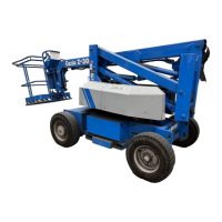
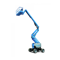
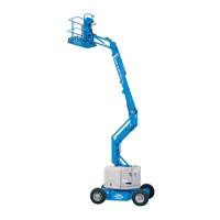
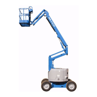
| Brand | Genie |
|---|---|
| Model | Z-45/22 |
| Category | Boom Lifts |
| Language | English |