Do you have a question about the Genie Z-45 XC and is the answer not in the manual?
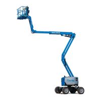
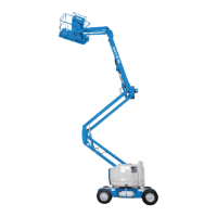
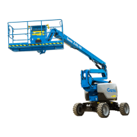
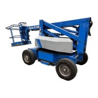
Key safety and operating instructions for the Genie Z-45/25 & Z-45/25J.
Genie Industries contact details for inquiries and technical support.
General safety guidelines for safe operation and maintenance procedures.
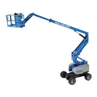
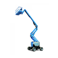
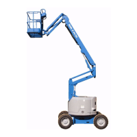
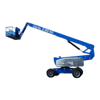
Detailed dimensions, weight, and turning radius of the machine.
Drive speeds, gradeability, and boom function speeds.
Fluid types, pump capacities, pressure ratings, and filter specifications.
Details for Ford, Deutz, and Perkins engine models, including lubrication.
Torque values for hydraulic hose and fitting installations.
Information on engine options (gasoline/LPG, diesel) and their power ratings.
Explanation of the hydraulic system's function, components, and pressure ratings.
Description of electrical controls for boom, steer, and drive functions.
Explanation of drive speed and drive enable limit switches.
Overview of ground and platform control systems and their functions.
Critical rules for performing repair and maintenance procedures safely.
Provides an overview of the scheduled maintenance procedures section.
Explanation of symbols used throughout the maintenance procedures.
Explanation of symbols used in maintenance procedures.
Schedule for daily, quarterly, six months, annual, and two-year inspections.
Checklists for recording results of scheduled maintenance inspections.
Detailed procedures for daily scheduled maintenance tasks.
Detailed procedures for general inspections and component checks.
Detailed procedures for Deutz and Perkins engine maintenance.
Detailed procedures for boom and turntable component maintenance.
Detailed procedures for engine and hydraulic system maintenance.
Guides for diagnosing and resolving machine malfunctions using flow charts.
Critical rules for performing troubleshooting and repair procedures safely.
Prerequisites and safety precautions before starting troubleshooting.
A general overview of the steps involved in the repair process.
Information on engine fault codes stored by the ECM.
Troubleshooting steps for an engine that will not crank.
Troubleshooting steps for Ford models where the engine cranks but won't start.
Troubleshooting steps for an engine that runs while cranking then dies.
Troubleshooting steps for diesel models where the engine cranks but won't start.
Troubleshooting for Ford models when engine starts on gasoline but not LPG.
Troubleshooting for Ford models when engine starts on LPG but not gasoline.
Troubleshooting steps for inoperative high idle function on Ford models.
Troubleshooting steps for inoperative low idle function on Ford models.
Troubleshooting steps for inoperative high idle function on diesel models.
Troubleshooting steps for inoperative low idle function on diesel models.
Troubleshooting when all functions are inoperative but the engine runs.
Troubleshooting when lift/steer functions are inoperative but drive functions work.
Troubleshooting when ground controls are inoperative but platform controls work.
Troubleshooting when platform controls are inoperative but ground controls work.
Troubleshooting steps for an inoperative primary boom up function.
Troubleshooting for primary boom down function inoperative before serial number 13099.
Troubleshooting for primary boom down function inoperative after serial number 13098.
Troubleshooting steps for an inoperative secondary boom up function.
Troubleshooting steps for an inoperative secondary boom down function.
Troubleshooting steps for an inoperative primary boom extend function.
Troubleshooting steps for an inoperative primary boom retract function.
Troubleshooting steps for an inoperative turntable rotate left function.
Troubleshooting steps for an inoperative turntable rotate right function.
Troubleshooting for when all platform leveling functions are inoperative.
Troubleshooting steps for an inoperative platform level up function.
Troubleshooting steps for an inoperative platform level down function.
Diagrams illustrating the machine's electrical and hydraulic systems.
Provides an overview of the schematics section.
Diagrams illustrating the electrical system of the machine.
Diagrams illustrating the hydraulic system of the machine.
List and specifications of electrical components used in the machine.
Explanation of symbols used in electrical schematics.
Glossary of abbreviations used in the schematics.
Wiring diagram for Ford LRG-425 EFI engine harness before serial number 13099.
Wiring diagram for Ford LRG-425 EFI engine harness after serial number 13098.
Electrical schematic for Z-45/25 Ford models before serial number 13099.
Electrical schematic for Z-45/25 Ford models from serial number 13099 to 16303.
Wiring diagram for ground control box on Z-45/25 Ford models before serial number 13099.
Wiring diagram for platform control box on Z-45/25 Ford models before serial number 13099.
Electrical schematic for Z-45/25J Ford models before serial number 13099.
Wiring diagram for ground control box on Z-45/25J Ford models before serial number 13099.
Wiring diagram for platform control box on Z-45/25J Ford models before serial number 13099.
Electrical schematic for Z-45/25J Ford models from serial number 13099 to 16303.
Wiring diagram for ground control box on Z-45/25J Ford models from serial number 13099 to 16303.
Wiring diagram for platform control box on Z-45/25J Ford models from serial number 13099 to 16303.
Electrical schematic for Z-45/25 Deutz models before serial number 13099.
Wiring diagram for ground control box on Z-45/25 Deutz models before serial number 13099.
Wiring diagram for platform control box on Z-45/25 Deutz models before serial number 13099.
Electrical schematic for Z-45/25J Deutz models from serial number 13099 to 16303.
Wiring diagram for ground control box on Z-45/25J Deutz models from serial number 13099 to 16303.
Wiring diagram for platform control box on Z-45/25J Deutz models from serial number 13099 to 16303.
Wiring diagram for platform control box with lift/drive select option for Deutz models after serial number 16303.
Electrical schematic for Z-45/25 Perkins models before serial number 16304.
Wiring diagram for ground control box on Perkins models before serial number 16304.
Wiring diagram for platform control box on Perkins models before serial number 16304.
Electrical schematic for Z-45/25J Perkins models before serial number 16304.
Wiring diagram for ground control box on Z-45/25J Perkins models before serial number 16304.
Wiring diagram for platform control box on Z-45/25J Perkins models before serial number 16304.
Wiring diagram for platform control box with lift/drive select option for Z-45/25J Perkins models after serial number 16303.
Electrical schematic for Z-45/25 Deutz models after serial number 16303.
Wiring diagram for ground control box on Z-45/25 Deutz models after serial number 16303.
Wiring diagram for platform control box on Z-45/25 Deutz models after serial number 16303.
Wiring diagram for platform control box with lift/drive select option for Z-45/25J Deutz models after serial number 16303.
Electrical schematic for Z-45/25J Deutz models after serial number 16303.
Wiring diagram for ground control box on Z-45/25J Deutz models after serial number 16303.
Wiring diagram for platform control box on Z-45/25J Deutz models after serial number 16303.
Wiring diagram for platform control box with lift/drive select option for Z-45/25J Deutz models after serial number 16303.
Electrical schematic for Z-45/25 Perkins models after serial number 16303.
Wiring diagram for ground control box on Z-45/25 Perkins models after serial number 16303.
Wiring diagram for platform control box on Z-45/25 Perkins models after serial number 16303.
Wiring diagram for platform control box with lift/drive select option for Z-45/25J Perkins models after serial number 16303.
Hydraulic schematic illustrating the 2WD drive system.
Hydraulic schematic illustrating the 4WD drive system.
Detailed instructions for performing repairs on machine components.
Critical rules for performing repair procedures safely.
Prerequisites and safety precautions before starting repairs.
Explanation of symbols used in repair procedures.
Procedures related to the operation and adjustment of platform controls.
Maintaining joystick controllers for proper settings and smooth operation.
Adjusting primary boom up/down controller trim potentiometers for correct operation.
Adjusting secondary boom up/down controller trim potentiometers for correct operation.
Adjusting turntable rotation controller trim potentiometers for proper speed and cycle time.
Understanding and adjusting the horsepower limiter board for drive pump output.
Step-by-step guide for adjusting the horsepower limiter board.
Procedures for testing the foot switch functionality.
Step-by-step guide to test the foot switch for continuity.
Information on toggle switches and how to test them.
Procedure to test toggle switches for continuity.
Procedures for removing the platform.
Step-by-step guide to safely remove the platform.
Procedures for removing and bleeding the platform leveling slave cylinder.
Step-by-step guide to remove the slave cylinder.
Procedure to remove air from the slave cylinder hydraulic system.
Procedures for removing the platform rotator.
Step-by-step guide to remove the platform rotator.
Procedure to bleed air from the platform rotator hydraulic system.
Procedures for removing the jib boom from Z-45/25J models.
Step-by-step guide to safely remove the jib boom.
Procedures for removing the jib boom lift cylinder.
Step-by-step guide to safely remove the jib boom lift cylinder.
Identification and torque specifications for manifold components.
Procedures for removing and repairing the primary boom cable track.
Step-by-step guide to remove the cable track.
Method for repairing the primary boom cable track using a kit.
Procedures for shimming and removing the primary boom.
Steps to shim primary boom wear pads for proper clearance.
Step-by-step guide to safely remove the primary boom.
Procedure for complete boom disassembly when necessary.
Procedures for removing the primary boom lift cylinder.
Step-by-step guide to safely remove the primary boom lift cylinder.
Procedures for removing the primary boom extension cylinder.
Step-by-step guide to safely remove the extension cylinder.
Procedures for removing the platform leveling master cylinder.
Step-by-step guide to safely remove the master cylinder.
Procedures for disassembling the secondary boom.
Step-by-step guide for safely disassembling the secondary boom.
Procedures for removing the secondary boom lift cylinders.
Step-by-step guide to safely remove a secondary boom lift cylinder.
Procedures for removing turntable covers.
Step-by-step guide to safely remove turntable covers.
Repair procedures specific to the Deutz F3L 1011F engine.
Procedure to adjust engine RPM.
Procedures for removing and installing the flex plate.
Repair procedures specific to the Perkins 104-22 engine.
Procedure to adjust engine RPM.
Procedures for removing and installing the flex plate.
Procedures for removing and installing coolant and oil pressure sending units.
Repair procedures specific to the Ford LRG-425 EFI engine.
Procedure for adjusting ignition timing.
Procedure to adjust engine RPM.
Procedures for removing and installing the flex plate.
Procedures for removing and installing water temperature and oil pressure switches.
Step-by-step guide to remove and replace switches.
Procedures related to the ground control system.
Procedures for testing single pole double throw relays.
Diagrams illustrating the electrical and hydraulic systems of the machine.
List and specifications of electrical components used in the machine.
Explanation of symbols used in electrical schematics.
Glossary of abbreviations used in the schematics.
Wiring diagram for Ford LRG-425 EFI engine harness before serial number 13099.
Wiring diagram for Ford LRG-425 EFI engine harness after serial number 13098.
Electrical schematic for Z-45/25 Ford models before serial number 13099.
Electrical schematic for Z-45/25 Ford models from serial number 13099 to 16303.
Wiring diagram for the ground control box on Z-45/25 Ford models before serial number 13099.
Wiring diagram for the platform control box on Z-45/25 Ford models before serial number 13099.
Electrical schematic for Z-45/25J Ford models before serial number 13099.
Wiring diagram for the ground control box on Z-45/25J Ford models before serial number 13099.
Wiring diagram for the platform control box on Z-45/25J Ford models before serial number 13099.
Electrical schematic for Z-45/25J Ford models from serial number 13099 to 16303.
Wiring diagram for the ground control box on Z-45/25J Ford models from serial number 13099 to 16303.
Wiring diagram for the platform control box on Z-45/25J Ford models from serial number 13099 to 16303.
Electrical schematic for Z-45/25 Deutz models before serial number 13099.
Wiring diagram for the ground control box on Z-45/25 Deutz models before serial number 13099.
Wiring diagram for the platform control box on Z-45/25 Deutz models before serial number 13099.
Electrical schematic for Z-45/25J Deutz models from serial number 13099 to 16303.
Wiring diagram for the ground control box on Z-45/25J Deutz models from serial number 13099 to 16303.
Wiring diagram for the platform control box on Z-45/25J Deutz models from serial number 13099 to 16303.
Wiring diagram for platform control box with lift/drive select option for Deutz models after serial number 16303.
Electrical schematic for Z-45/25 Perkins models before serial number 16304.
Wiring diagram for ground control box on Perkins models before serial number 16304.
Wiring diagram for platform control box on Perkins models before serial number 16304.
Electrical schematic for Z-45/25J Perkins models before serial number 16304.
Wiring diagram for ground control box on Z-45/25J Perkins models before serial number 16304.
Wiring diagram for platform control box on Z-45/25J Perkins models before serial number 16304.
Wiring diagram for platform control box with lift/drive select option for Z-45/25J Perkins models after serial number 16303.
Electrical schematic for Z-45/25 Deutz models after serial number 16303.
Wiring diagram for ground control box on Z-45/25 Deutz models after serial number 16303.
Wiring diagram for platform control box on Z-45/25 Deutz models after serial number 16303.
Wiring diagram for platform control box with lift/drive select option for Z-45/25J Deutz models after serial number 16303.
Electrical schematic for Z-45/25J Deutz models after serial number 16303.
Wiring diagram for ground control box on Z-45/25J Deutz models after serial number 16303.
Wiring diagram for platform control box on Z-45/25J Deutz models after serial number 16303.
Wiring diagram for platform control box with lift/drive select option for Z-45/25J Deutz models after serial number 16303.
Electrical schematic for Z-45/25 Perkins models after serial number 16303.
Wiring diagram for ground control box on Z-45/25 Perkins models after serial number 16303.
Wiring diagram for platform control box on Z-45/25 Perkins models after serial number 16303.
Wiring diagram for platform control box with lift/drive select option for Z-45/25J Perkins models after serial number 16303.
Hydraulic schematic illustrating the 2WD drive system.
Hydraulic schematic illustrating the 4WD drive system.
Detailed instructions for performing repairs on machine components.
Critical rules for performing repair procedures safely.
Prerequisites and safety precautions before starting repairs.
Explanation of symbols used in repair procedures.
Procedures related to the operation and adjustment of platform controls.
Maintaining joystick controllers for proper settings and smooth operation.
Adjusting primary boom up/down controller trim potentiometers for correct operation.
Adjusting secondary boom up/down controller trim potentiometers for correct operation.
Adjusting turntable rotation controller trim potentiometers for proper speed and cycle time.
Understanding and adjusting the horsepower limiter board for drive pump output.
Step-by-step guide for adjusting the horsepower limiter board.
Procedures for testing the foot switch functionality.
Step-by-step guide to test the foot switch for continuity.
Information on toggle switches and how to test them.
Procedure to test toggle switches for continuity.
Procedures for removing the platform.
Step-by-step guide to safely remove the platform.
Procedures for removing and bleeding the platform leveling slave cylinder.
Step-by-step guide to remove the slave cylinder.
Procedure to remove air from the slave cylinder hydraulic system.
Procedures for removing the platform rotator.
Step-by-step guide to remove the platform rotator.
Procedure to bleed air from the platform rotator hydraulic system.
Procedures for removing the jib boom from Z-45/25J models.
Step-by-step guide to safely remove the jib boom.
Procedures for removing the jib boom lift cylinder.
Step-by-step guide to safely remove the jib boom lift cylinder.
Identification and torque specifications for manifold components.
Procedures for removing and repairing the primary boom cable track.
Step-by-step guide to remove the cable track.
Method for repairing the primary boom cable track using a kit.
Procedures for shimming and removing the primary boom.
Steps to shim primary boom wear pads for proper clearance.
Step-by-step guide to safely remove the primary boom.
Procedure for complete boom disassembly when necessary.
Procedures for removing the primary boom lift cylinder.
Step-by-step guide to safely remove the primary boom lift cylinder.
Procedures for removing the primary boom extension cylinder.
Step-by-step guide to safely remove the extension cylinder.
Procedures for removing the platform leveling master cylinder.
Step-by-step guide to safely remove the master cylinder.
Procedures for disassembling the secondary boom.
Step-by-step guide for safely disassembling the secondary boom.
Procedures for removing the secondary boom lift cylinders.
Step-by-step guide to safely remove a secondary boom lift cylinder.
Procedures for removing turntable covers.
Step-by-step guide to safely remove turntable covers.
Repair procedures specific to the Deutz F3L 1011F engine.
Procedure to adjust engine RPM.
Procedures for removing and installing the flex plate.
Repair procedures specific to the Perkins 104-22 engine.
Procedure to adjust engine RPM.
Procedures for removing and installing the flex plate.
Procedures for removing and installing coolant and oil pressure sending units.
Repair procedures specific to the Ford LRG-425 EFI engine.
Procedure for adjusting ignition timing.
Procedure to adjust engine RPM.
Procedures for removing and installing the flex plate.
Procedures for removing and installing water temperature and oil pressure switches.
Step-by-step guide to remove and replace switches.
Procedures related to the ground control system.
Procedures for testing single pole double throw relays.
Step-by-step guide to test control relays.
Reference to toggle switch testing procedures.
Procedures for handling Wago® components.
Procedure to retrieve and interpret engine fault codes.
Step-by-step guide to retrieve engine fault codes from the ECM.
Procedure to reset the ECM memory and clear fault codes.
Procedures for servicing hydraulic pumps.
Procedures for removing and priming the lift/steer pump.
Step-by-step guide to remove the lift/steer pump.
Procedure to prime the hydraulic pump after installation.
Procedures for removing and priming the drive pump.
Step-by-step guide to remove the drive pump.
Component identification and torque specifications for function and drive manifolds.
Identification and torque specifications for function manifold components.
Procedures for adjusting relief and regulator valves in the function manifold.
Steps to adjust the system relief valve pressure.
Steps to adjust the primary boom down relief valve.
Steps to adjust the secondary boom down relief valve.
Resistance specifications for valve coils.
Identification and torque specifications for turntable rotation manifold components.
Identification of directional valve manifold components.
Procedure for setting up directional valve linkage alignment.
Identification and torque specifications for 2WD drive manifold components.
Procedure for adjusting the charge pressure relief valve in the 2WD drive manifold.
Steps to adjust the charge pressure relief valve.
Identification and torque specifications for 4WD drive manifold components.
Procedure for adjusting the charge pressure relief valve in the 4WD drive manifold.
Steps to adjust the charge pressure relief valve.
Procedures for removing fuel and hydraulic tanks.
Procedures for removing the fuel tank.
Step-by-step guide to safely remove the fuel tank.
Procedures for removing the hydraulic tank.
Step-by-step guide to safely remove the hydraulic tank.
Procedures for removing the rotation hydraulic motor and brake.
Procedures for removing the rotation hydraulic motor.
Step-by-step guide to safely remove the motor.
Procedures for removing the turntable rotation brake.
Procedures for servicing steering axle components.
Procedures for removing the yoke and hub.
Step-by-step guide to safely remove the yoke and hub.
Procedures for removing the hub and bearings.
Procedures for removing steering cylinders.
Step-by-step guide to safely remove a steering cylinder.
Procedures for removing the tie rod.
Step-by-step guide to remove the tie rod.
Procedures for removing the yoke and hub.
Step-by-step guide to safely remove the yoke and hub.
Reference to steering cylinder removal procedure.
Reference to tie rod removal procedure.
Procedures for removing oscillating axle lock-out cylinders.
Procedures for removing the lock-out cylinders.
Step-by-step guide to safely remove the cylinder.
Procedures for servicing drive motor and drive hub.
Procedures for removing the drive motor.
Step-by-step guide to safely remove the drive motor.
Procedures for removing the drive hub.
Step-by-step guide to safely remove the drive hub.
| Weight | 15, 400 lb (7, 000 kg) |
|---|---|
| Gradeability - 4WD | 45% |
| Power Source | Diesel |
| Ground Clearance | 12 in |
| Platform Dimensions | 72 in x 30 in |