BRAIN 15
ENGLISH
Guide for the installer
Page 19
6. Give an OPEN impulse, leaves will move and the BUS
learning procedure is over.
The board has memory stored the BUS accessories. Follow the
instructions in the table below to check if the BUS connection is
correct.
Tab. 6 - Description of BUS LED
Steady light
Normal operation (LED ON even in the
absence of photocells)
Slow fl ashing lamp
(fl ash every 0.5 sec)
At least one input engaged: photocell
engaged or not aligned, Open A or Open
B or Stop input engaged
Light OFF
(fl ash every 2.5 sec)
BUS line short circuited
Fast flashing lamp
(fl ash every 0.2 sec)
If you have detected a BUS connection
error, repeat the acquisition procedure.
If the error is repeated, make sure that
there is not more than one accessory
with the same address in the system
(also see the accessories instructions)
7.3. Memorising the BUS encoder
To connect an encoder (optional) to the system with BUS techno-
logy, just connect the two wires of the encoder to the J10 terminal
block. If there are two motors, the encoder cannot be installed on
one motor alone.
The terminal board does not have a specifi c polarity, however
the connection sequence determines which leaf the encoder is
associated to. To verify the correct leaf-encoder combination, look
at the status of LED DL2.
DL1
DL2
DL3
J10
The table below describes the meanings of the various LEDs
located on the encoder.
LED ON FLASHING OFF
DL1
Powered and BUS
communicating
with board
Powered but
BUS not
communicating
(e.g.: wiring error)
No BUS power or
communication
(e.g.: no
connection or
connection
interrupted)
DL2
Encoder
associated to
leaf 1
/
Encoder
associated to
leaf 2
DL3 /
Pulse reading
during leaf
movement
Leaf not moving
To invert the association of the encoders, just swap the poles of
the cables.
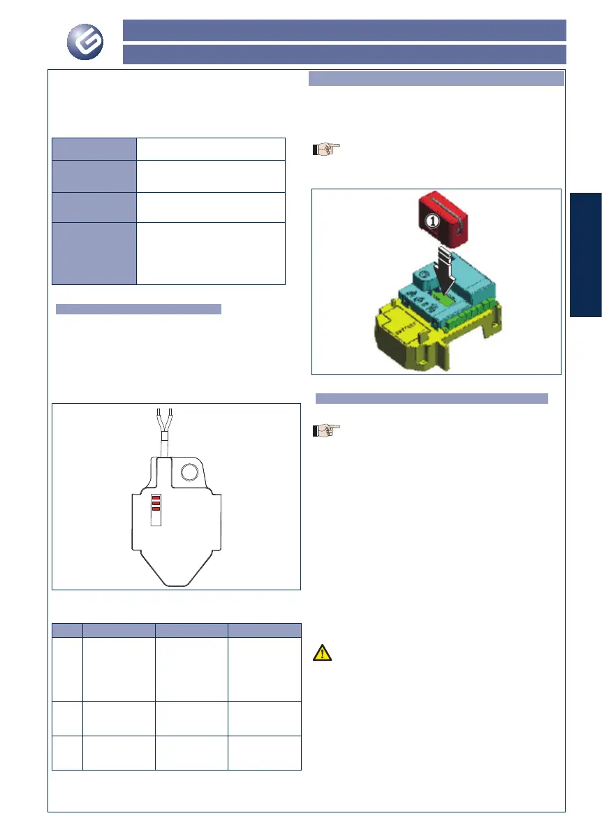
8. MEMORY STORING THE RADIO CODE
The control board has an integrated 2-channel decoding system.
This system makes it possible to memory-store both total opening
(OPEN A) and partial opening OPEN B) of the automated system
- this is made possible by an additional receiver module (fi g.3 ref.
) and radio controls on the same frequency.
• Only one radio code can be used at a time.
• To change over from one code to another, you must
delete the existing one (see paragraph on deletion),
and repeat the memory-storage procedure.
Fig. 3
8.1. Memory storage of - JLC (Amigo-Kilo) radio
controls
A maximum of 250 codes can be memory stored, split
between OPEN A and OPEN B.
1. On the radio control, simultaneously press and hold down
push-buttons P1 and P2.
2. The radio control LED begins to fl ash.
3. Release both push-buttons.
4. Press the LOGIC (SW3) or SPEED (SW2) push-button, to
memory store respectively total opening (OPEN A) or partial
opening (OPEN B), and as you hold it down, also press the
SETUP (SW1) push-button. The relevant LED starts to fl ash
slowly for 5 sec.
5. Release both push-buttons.
6. Within these 5 sec., while the radio control LED is still
fl ashing, press and hold down the required push-button
on the radio control (the radio control LED lights up on
steady beam).
7. The LED on the board lights up on steady beam for 1 second
and then goes OFF, indicating that storage was executed.
8. Release the radio control push-button.
9. Quickly press twice the memory stored radio control push-
button.
The automated system performs one opening operation.
Make sure that the automated system is free of any
obstacle created by persons or things.
To add other radio controls, transfer the code of the memory-stored
push-button of the radio control to the relevant push-button of the
radio controls to be added, observing the following procedure:
• On the memory stored radio control, simultaneously press and
hold down push-buttons P1 and P2.
• The radio control LED begins to fl ash.
• Release both push-buttons.
• Press the memory stored push-button and hold it down (the radio
control LED lights up on steady beam).
• Bring the radio controls near, press and hold down the push-
button of the radio control to be added, releasing it only after the
double fl ash of the radio control LED, which indicates memory
 Loading...