BRAIN 15
ENGLISH
Guide for the installer
Page 18
7.INSTALLATION OF BUS ACCESSORIES
This board is supplied with a BUS circuit enabling easy connection
of a high number of BUS accessories (e.g. up to 16 photocells pairs),
appropriately programmed, using only two cable without polarity.
Below we describe the addressing and memory storage of the
BUS photocells.
For other future accessories, refer to the specifi c instructions.
7.1. Addressing the BUS photocells
The same address must be given to both transmitter and
receiver.
Make sure that there are no two or more photocells pairs
with the same address.
If no BUS accessory is used, leave the BUS connector
free (J10 - fi g. 1).
A maximum of 16 BUS photocell pairs can be connected to the
board.
The photocells are split into groups:
Opening photocells Max. 6
Closing photocells Max. 7
Opening /Closing photocells Max. 2
Photocell used as an OPEN pulse Max. 1
Fig. 2
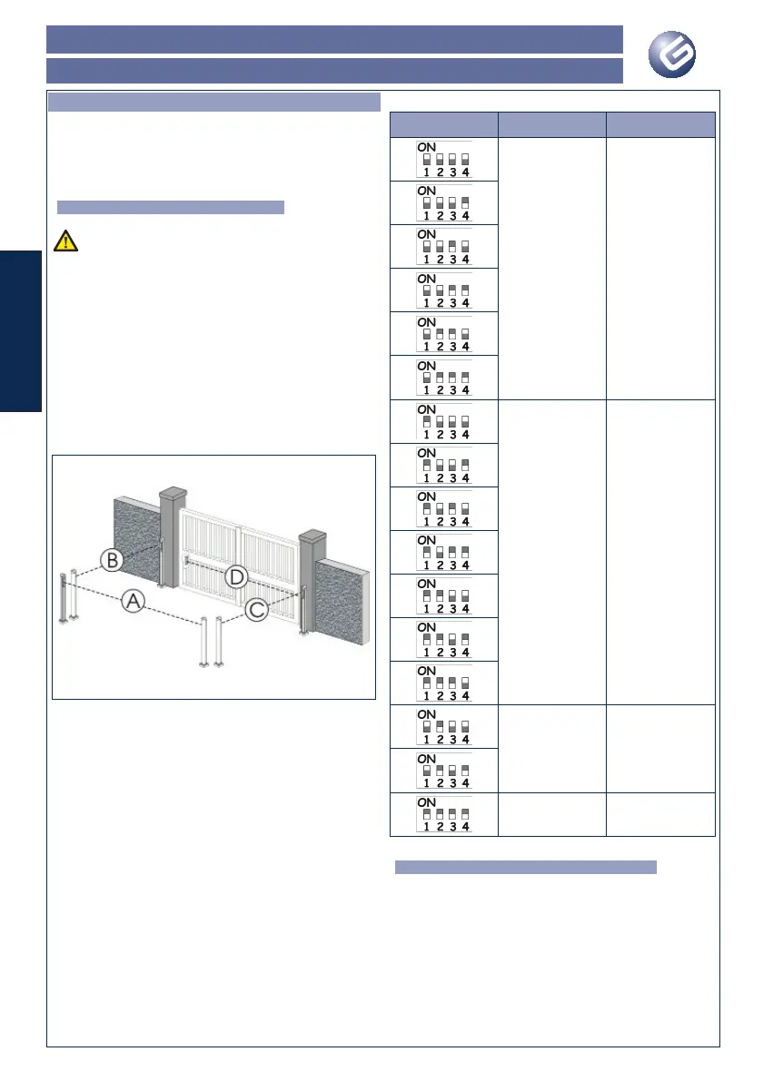
Fig. 2 shows a 2-swing leaf automated system indicating the
coverage beams of the photocells:
A: Photocells with OPENING and CLOSING action.
B: Photocells with OPENING action
C: Photocells with OPENING action
D: Photocells with CLOSING action
Table 5 shows the programming operations of the dip-switch inside
the transmitter and of the BUS Photocells receiver.
Tab. 5 - Addressing of BUS Photocells
Dip1 Rif. Tipologia
B - C OPENING
D CLOSING
A
OPENING and CLO-
SING
/ OPEN PULSE
7.2. Memory storage of BUS accessotries
You can add the BUS photocells to the system at any time, simply
by memory-storing them on the board, observing the following
procedure:
1. Install and program the accessories using the required
address (see paragraph 7.1)
2. Cut power to the board.
3. Connect the two accessories cables to the red terminal-board
J10 (any polarity will do).
4. Power up the board, taking care to fi rst connect the main
power supply (transformer output) and then any batteries.
5. Quickly press once only the SW1 (SETUP) push-button, to
execute learning. The BUS LED fl ashes.
 Loading...