BRAIN 15
ENGLISH
Guide for the installer
Page 20
storage executed.
• Quickly press twice the push-button of the memory stored
radio control.
The automated system performs one opening operation.
Make sure that the automated system is free of any
obstacle created by persons or things.
8.2. Memory storage of 433 RC (Bravo - Echo) radio
controls
A maximum of 250 codes can be memory stored, split
between OPEN A and OPEN B.
1. Use 433 RC (Bravo - Echo) remote controls only with receiver
module at 433 RC (Bravo - Echo) MHz.
2. Press the LOGIC (SW3) or SPEED (SW2) push-button, to
memory store respectively total opening (OPEN A) or partial
opening (OPEN B), and as you hold it down, also press the
SETUP (SW1) push-button. The relevant LED starts to fl ash
slowly for 5 sec.
3. Release both push-buttons. Within these 5 sec., press the
appropriate push-button on the remote control.
4. The LED lights up on steady beam for 1 second, indicating
memory storage executed, and then resumes fl ashing for
another 5 sec., during which another radio control (point 4)
can be memory stored.
5. When the 5 sec. have elapsed, the LED goes OFF indicating
the end of the procedure.
6. To add other radio controls, repeat the operation at point 1.
8.2.1. REMOTE MEMORY STORAGE OF 433 RC (BRAVO - ECHO)
RADIO CONTROLS
Other radio controls can be remotely stored only with the 433 RC
(Bravo - Echo) radio controls, i.e. without using the LOGIC-SPEED-
SETUP push-buttons, but using a previously stored radio control.
1. Get a radio control already stored on one of the 2 channels
(OPEN A or OPEN B ).
2. Press and hold down push-buttons P1 and P2 simultaneously
until both the LEDs fl ash slowly for 5 sec.
3. Within 5 sec. press the push-button of the radio control
that had been memory stored to enable learning on the
selected channel.
4. The LED on the board relating to the channel being learned
fl ashes for 5 sec., within which time the code of another radio
control must be transmitted.
5. The LED lights up on steady beam for 2 seconds, indicating
memory storage executed, and then resumes fl ashing for
5 sec., during which other radio controls can be memory
stored, and then goes OFF.
8.3. Radio controls deletion procedure
To delete ALL the input radio control codes, press push-button
LOGIC (SW3) or SPEED (SW2) and, while holding it down, also
press push-button SETUP (SW1) for 10 sec.
1. The LED relating to the pressed push-button fl ashes for the
fi rst 5 sec, and then fl ashes more quickly for the next 5 sec.
2. Both LEDs light up on steady beam for 2 sec and then go
OFF (deletion completed).
3. Release both push-buttons.
This operation is NOT reversible. All codes of radio con-
trols stored as OPEN A and OPEN B will be deleted.
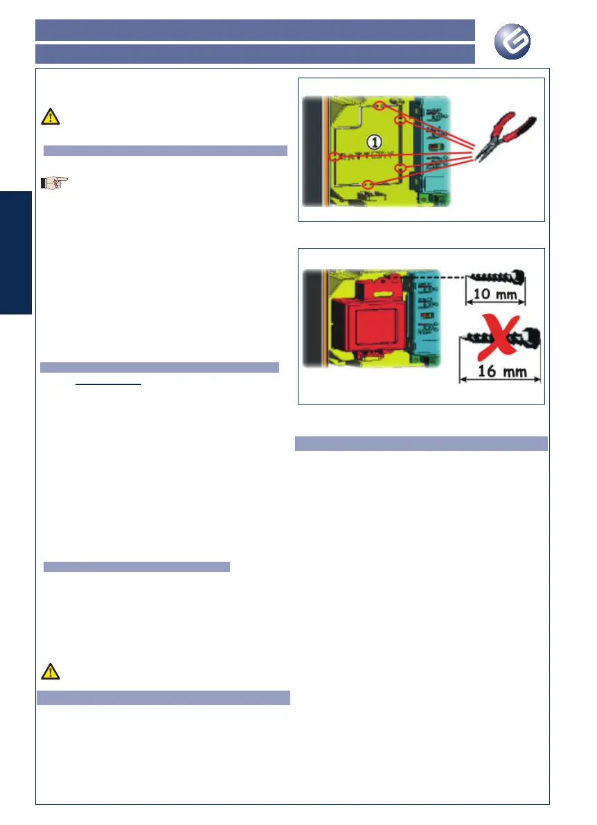
9. BATTERY KIT (OPZIONAL)
The buffer battery kit was built for insertion inside the control
board support.
This support (Fig.4 ref. ) was pre-moulded to permit the battery
housing to be opened.
1. Remove the board support material covering the battery
housing, cutting the material connections along the perimeter.
Fig. 4
2. Insert the battery in the housing you have just created, and
secure it on the anchoring supports (Fig. 5).
Fig. 5
3. To correctly fasten and connect the kit to the control unit,
consult the instructions enclosed with the battery kit.
10. AUTOMATED SYSTEM TEST
When you have fi nished programming, check if the system is
operating correctly. In particular, check if the safety devices are
operating correctly.
 Loading...