BRAIN 15
ENGLISH
Guide for the installer
Page 15
3. TECHNICAL SPECIFICATIONS
Power supply voltage
230Vac (+6% -10%) - 50Hz
or
115Vac (+6% -10%) - 60Hz
Supply voltage of control unit
24 Vac nominal
Absorbed power 4W
Motor max. load 150W x 2
Accessories max. current (+24V) 250 mA
BUS Accessories max.current 400 mA
Operating ambient temperature -20°C... +55°C
Fuses
F1 = self-resetting;
F2 = T2A-250V
or
T4A-120V
Function logics A, E, AP, EP,A1,B,C
Work time (time-out) 1 minute (maximum)
Pause time
Varies according to learning
(max. 10 min.)
Terminal board inputs
Open A, Open B, Stop, BUS
(I/O)
Connector inputs
Power supply, battery radio
module 3 pins
Terminal board outputs
Motors, fl ashing lamp, power
supply to accessories, electric
lock, service light contact (90
sec fi xed)
Programmable functions
Logic (A, E, AP, EP,A1,B,C),
Speed (High - Low)
Learning functions
Pause time,
leaf closing delay
The power supply and the fuse are related to the
purchased version.
Different output values can be obtained on the board
supply terminals depending on the mains voltage va-
lue. Before start-up always check if the output voltage
on the transformer secondary winding is between 20
Vac and 26 Vac. Voltage must be measured load free.
3.1. Description of components
J1 POWER SUPPLY connector
J2 SERVICE LIGHT command terminal-board
J3 FLASHING LAMP terminal-board
J4 ELECTRIC LOCK terminal-board
J5 COMMANDS terminal-board
J7 MOTOR 1 terminal-board
J8 MOTOR 2 terminal-board
J9 Rapid connection for RADIO MODULE 3 pins
J10 BUS terminal-board
J11 BATTERY connector
SW1 SET UP push-button
SW2 SPEED push-button
SW3 LOGIC push-button
DS1 Programming Dip-switch
F1 Accessories protective fuse
F2 Fuses protecting transformers and motors
LED Signalling LEDs
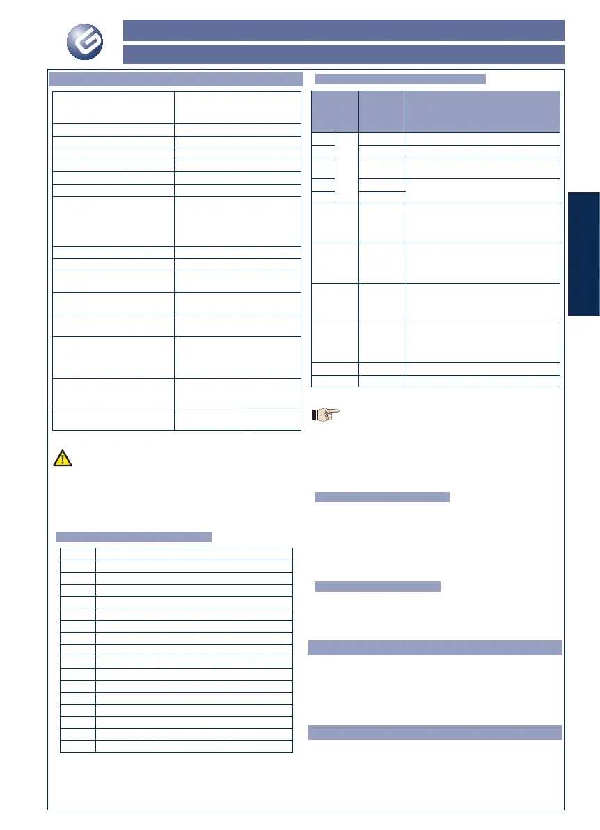
3.2. Description of terminal-boards
Terminal
and/or
terminal-
board
Descrip-
tion
Device connected
1
J5
+24V Power supply for accessories
2 GND Negative
3STOP
Device with NC contact which causes the
automated system to shut down
4 OPEN B
Device with N.O contact (see chap. FUN-
CTION LOGICS)
5 OPEN A
J10
RED
terminal
BUS Safety devices with BUS technology
J2
GREY
terminal
SERVICE
LIGHT
Service Light control output (connect a
relay coil at 24Vdc-100mA max)
J3
ORANGE
terminal
LAMP Flashing lamp 24Vdc - 15W
J4
BLUE
terminal
LOCK
Electric lock 12Vac or 24 Vdc (to be
installed on leaf 1)
J7 MOT1 Motor 1 (leaf 1)
J8 MOT2 Motor 2 (leaf 2)
The service light control is active as specifi ed in advanced
function 9 Table 4:
- for the entire opening and closing movement of the gate
and for a further 90 seconds (standard operation)
- when the gate is closed (closed status function)
Leaf 1 means the leaf which opens fi rst during the opening
operation.
3.3. Anti-crushing function
The electronic anti-crushing function is obtained by controlling the
current consumption or the encoder of the motors connected to
the BRAIN 15 equipment.
If the gate detects an obstacle during the opening or closing move-
ment, the anti-crushing function activates and reverses the sense
of direction of the operator, thus increasing the safety degree of
the automated system.
3.4. Over pushing stroke
If you enable this function, at every OPEN pulse the leaf on which the
electric lock is installed starts its closing movement for a few seconds.
This facilitate release of the electric lock.
4. PROGRAMMING OF THE LOGIC
Repeatedly press the SW3 LOGIC push-button to select one of the
7 programming logics available.
The selected logic is signaled by the LD7 LED:
The number of blinkings corresponds to the number of the se-
lected logic.
See paragraph 6.3.3.
5. PROGRAMMING THE SPEED
The function speed can be adjusted at any time by pressing
push-button SW2.
The selected logic is then displayed on LED LD8:
Led on = HIGH speed
Led off = LOW speed
 Loading...