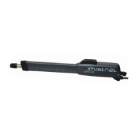
3. TECHNICAL SPECIFICATIONS
TECHNICAL SPECIFICATIONS MIHSTRAL T ENV
Power supply 24 Vdc
Motor nominal power (W) 35
Thrust (daN) 150
Capacitor (µF) /
Travel (mm) 300
Rod extension speed (cm/sec) From 1.6 to 2.1
Leaf max. (m)
a
3
Use frequency at 20°C 80 cycles/day
Consecutive cycles
b
30
Operating ambient temperature (°C) -20 +55
Operator weight (kg) 7.5
Operator dimensions See fig. 2
Protection class IP 54
a
The value indicated refers to a leaf with an electric lock. Without the use
of the electric lock, the max. leaf dimension is 2.5 m.
b
The maximum number of consecutive cycles is limited by software.
4. INSTALLATION
4.1. ELECTRICAL SET-UP (STANDARD SYSTEM)
•Use suitable tubes and/or hoses to lay electric cables
• To avoid any kind of interference always separate low-voltage ac-
cessories and control cables from 230/115 V~ power supply cables
using separate sheaths.
4.2. PRELIMINARY CHECKS
To ensure a correct operation of the automated system, make sure the
following requirements are observed as for the gate structure (existing or
to be created):
the mechanical parts must conform to the provisions of Standards EN
12604 and EN 12605.
leaf length in compliance with the operator specifications.
sturdy and stiff structure of the leaves, suitable for automation.
regular and uniform movement of the leaves, without any friction and
dragging during their entire opening.
with the reversible motors to verify that the gate does not move alone.
stiff hinges in good conditions.
presence of both opening and closing mechanical limit stops.
presence of an efficient earthing for electrical connection of the ope-
rator.
Perform any necessary metalwork job before installing the automa-
ted system.
The condition of the gate structure directly affects the reliability and
safety of the automated system.
�
�
•
•
•
•
•
•
•
•
Pos. Description
a
Operators
b
Photocells
c
Control board
d
Key push button
e
Flashing lamp
Pos. Description
a
Operators
b
Photocells
c
Control board
d
Key push button
e
Flashing lamp
Fig. 3Fig. 3
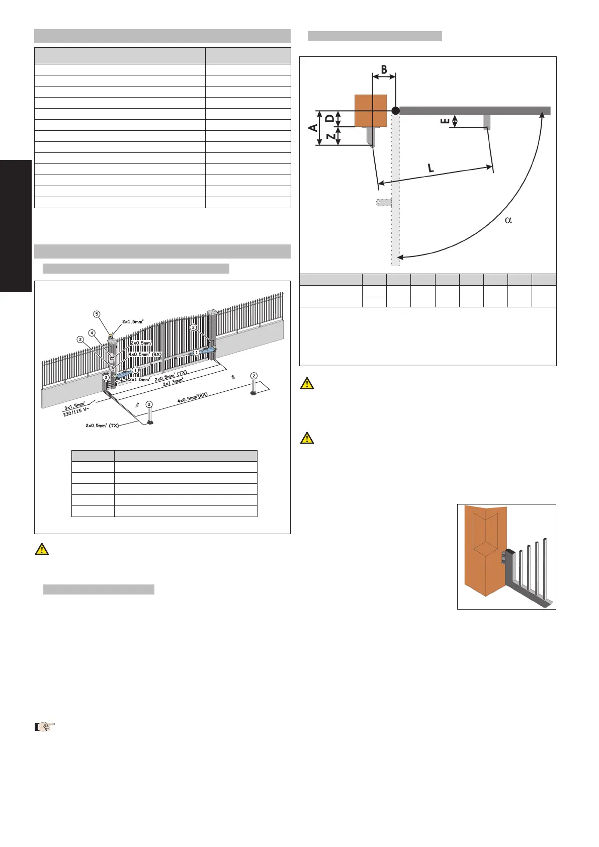
4.3. INSTALLATION DIMENSIONS
Determine the fitting position of the operator with reference to Fig. 4.
VCheck with care if the distance between the open leaf and any ob-
stacles (walls, fences etc.) is higher than the operator dimensions.
4.3.1. geneRal Rules to deteRmine the installation dimensions
To obtain 90° leaf openings : A+B=C
To obtain leaf openings exceeding 90° : A+B<C
• Smaller A and B dimensions determine higher peripheral speed of
the leaf.
• Limit the difference between A and B dimension within 4 cm: higher
differences cause great speed variations during the gate opening
and closing movement.
Keep a Z dimension in such a way that the operator does not strike the
pillar.
If the pillar dimensions or the hinge position
do not allow the installation of the opera-
tor, a niche on the pillar, as shown in Fig. 5,
should be created in order to maintain the A
dimension as determined. The niche should
be dimensioned in such a way to enable easy
installation, operator rotation and operation
of the release device.
•
•
•
Fig. 4Fig. 4
Model
a
A B
C
a
D
b
Z
c
L
E
c
MISTRAL ENV
90° 145 145 290 85
60 1110 45
110° 120 135 295 60
a
operator useful travel
b
max. dimension
c
min. dimension
Model
a
A B
C
a
D
b
Z
c
L
E
c
MISTRAL ENV
90° 145 145 290 85
60 1110 45
110° 120 135 295 60
a
operator useful travel
b
max. dimension
c
min. dimension
Fig. 5Fig. 5