circuits and fires or cause malfunctions of vehicle controls that can result in serious personal injury or significant damage to
your vehicle. Some examples requiring professional installation from an Authorized Geotab Installer are:
• The OBD port location is such that the device protrudes and interferes with entering or exiting the vehicle, or located
where it could be inadvertently kicked or bumped during vehicle operation
• The device isn't fully secured and so may come loose with vibrations or accidental contact
• An electrical harness or additional wiring is required
• Vehicle mounting modifications are required to secure the device, i.e. removing of panels; deformed/damaged OBD
connector; or physical damage to the electrical wiring
• The device does not beep six times and power on when first installed
• The installer questions their ability to complete a secure installation according to these instructions
WARNING! Do not attempt to install, reconfigure, or remove any product from a vehicle while the vehicle is in motion or
otherwise in operation. All installation, configuration, or removal must be done only in stationary vehicles which are securely
parked. Attempting to service devices while the vehicle is in motion could result in malfunctions or collisions, leading to death
or serious personal injury.
Please refer to the
GO9+ Installation FAQ if any questions during the installation process.
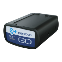
Installing the GO device
1 Locate the vehicle’s engine diagnostic port, typically found in the
driver’s area at or below knee level.
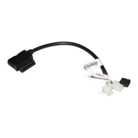
✱ NOTE: Heavy-duty trucks often use a different Diagnostic Link
Connector (DLC). Contact your Authorized Reseller to learn about
DLC applications for heavy-duty trucks, or how to use a vehicle-
specific harness if available.
2 Align the receiver end of the device with the engine diagnostic port
and push in place. Please ensure the device is connected to the
diagnostic port. Once connected, the device emits 6 quick beeps.
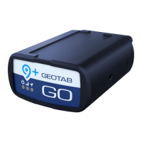
3 Once the device is connected and receives power, the LEDs on the
front of the device start blinking then turn solid once completing the
actions below:
Red LED — Device configuration
Green LED — Cellular network connectivity
Blue LED — GPS network connectivity
 Loading...