GV-AS400 Controller
49
3
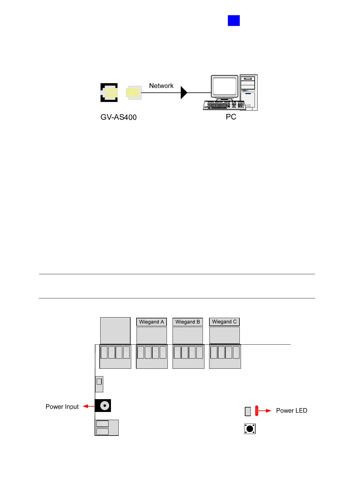
3.2.4 Connecting the PC
Figure 3-8
The connected computer is used to program GV-AS400. Also, the computer running GV-
ASManager software can be used to monitor the access information and alarm messages
from GV-AS400. If the computer is offline, GV-AS400 stores this information on the
database for later transmission.
3.2.5 Connecting the Power
The supplied AC adaptor can be connected to any power source supplying from 100 to 250V.
Using the supplied power cord and adaptor, connect GV-AS400 to the power. The power
LED on GV-AS400 should glow.
Note: Power should only be applied to the unit when all connections are completed and
tested.
GND
RS485 -
RS485 +
12V
GND
D1
D0
12V
GND
D1
D0
12V
GND
D1
D0
12V
Figure 3-9
 Loading...


