EasyManuals Logo

GeoVision GV-VD2400 User Manual

GeoVision GV-VD2400
723 pages
To Next Page IconTo Next Page
To Previous Page IconTo Previous Page
Page #153 background imageLoading...
Page #153 background image
Bullet Camera
9
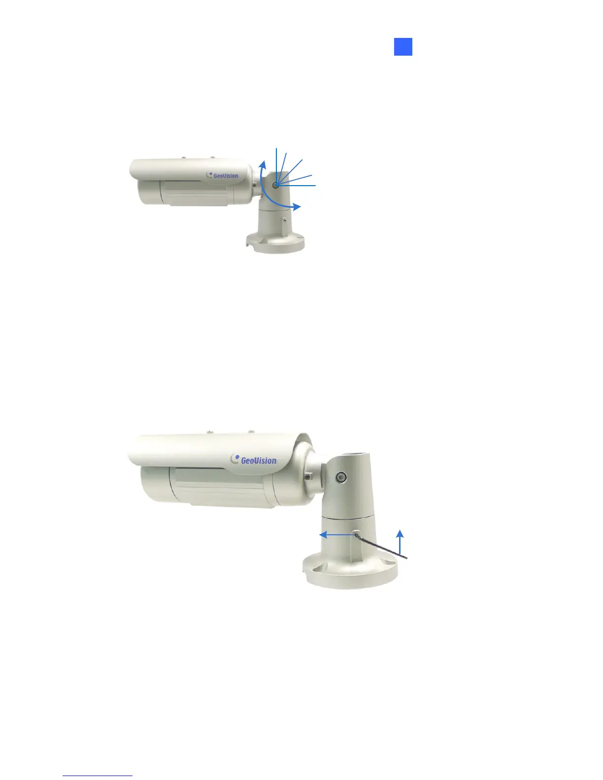
3. Adjust the angle of camera body to 90°, 112.5°, 135°, 157.5° or 180°.
Then move the camera base to the left to combine the gears.
90°
112.5°
180 °
157.5°
135 °
Figure 9-13
4. Fasten the tilting lock screw.
Third Shaft
You can adjust the camera base by 360°.
1. Unscrew the base fixing screw with the torx wrench.
Torx Wrench
Base Fixing Screw
Figure 9-14
119

Table of Contents

Other manuals for GeoVision GV-VD2400

Questions and Answers:

Question and Answer IconNeed help?

Do you have a question about the GeoVision GV-VD2400 and is the answer not in the manual?

GeoVision GV-VD2400 Specifications

General IconGeneral
BrandGeoVision
ModelGV-VD2400
CategoryIP Camera
LanguageEnglish

Related product manuals