EasyManuals Logo

GeoVision GV-VD2400 User Manual

GeoVision GV-VD2400
723 pages
To Next Page IconTo Next Page
To Previous Page IconTo Previous Page
Page #56 background imageLoading...
Page #56 background image
22
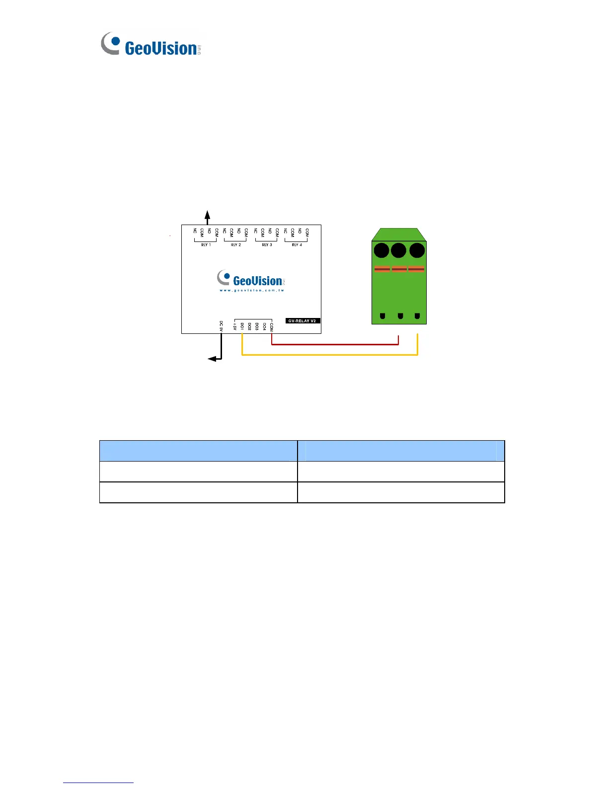
2.6.2 Connecting to GV-Relay V2 (Optional)
The Box Camera can only drive a maximum load of 200mA 5V DC. To
expand the maximum voltage load to 10A 250V AC, 10A 125V AC or 5A
100V DC, connect the camera to a GV-Relay V2 module (optional product).
Refer to the figure and table below.
Connect to Power
Output Device
I/O
123
Figure 2-7
GV-Relay V2 I/O Terminal Block
COM Pin 2 (GND)
DO1 Pin 3 (Digital Output)

Table of Contents

Other manuals for GeoVision GV-VD2400

Questions and Answers:

Question and Answer IconNeed help?

Do you have a question about the GeoVision GV-VD2400 and is the answer not in the manual?

GeoVision GV-VD2400 Specifications

General IconGeneral
BrandGeoVision
ModelGV-VD2400
CategoryIP Camera
LanguageEnglish

Related product manuals