14
English
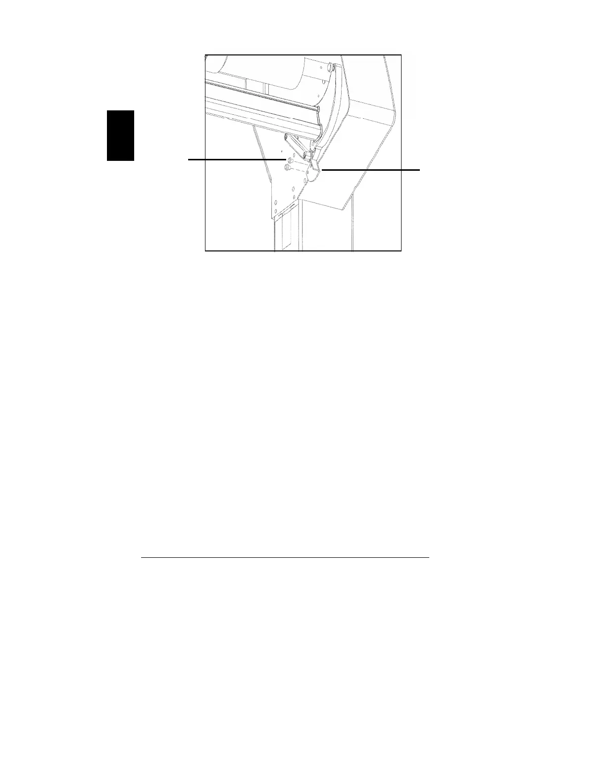
Figure 6. Nipbar Stop Installation
Key to Figure
1-M5 x 10 Screws (2 places each stop), 2-Nipbar Stop (2 places)
15. Remove these packing materials if present:
• plastic wrap securing plotter cover
• tie wrap securing the drive belt
CAUTION: Do not manually move the head
into the parking position or
damage to the plotter may result.
16. Manually move the plotter head to the mid-plotter position
to make sure it travels smoothly, but do not manually
move the head into the parking position.
1
2