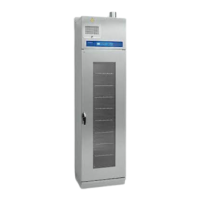
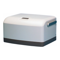
The Maquet Compressor Mini is a critical care device designed to supply medical-grade compressed air. It is a compact unit that can be placed on a ventilator cart or used as a stand-alone unit. The device is well-insulated against noise, making it suitable for use during operations without causing disturbance.
Function Description:
The Compressor Mini produces dry and clean compressed air. Ambient air is drawn into the compressor with a motor via an air inlet with a filter. The compressor heats the air, which then passes through a cooling coil for preliminary cooling before entering the thermoelectric cooler. The cooling coil is cooled by an air stream forced through the unit by a radial fan.
In the thermoelectric cooler, the air temperature is further lowered, causing moisture to condense into water. This water is separated from the air in the water separator and routed to a drainage bottle via a drainage valve. A pressure regulator ensures that the air pressure does not exceed a preset level (normally 450 kPa / 64 psi), with excess air being fed back to the compressor inlet. The dried, compressed air is collected in a 1.25-liter tank and routed to the compressed air outlet. The tank is equipped with a safety valve for emergency water removal.
The Compressor Mini features a standby function. It can be connected to a hospital central gas supply, and if the central supply fails, the compressor automatically starts to deliver compressed air. A standby valve switches between the central gas supply and the tank as the compressed air source.
The unit is fitted with temperature and pressure alarms. A temperature alarm activates if the compressor overheats or if there is a malfunction in the thermoelectric cooler. A pressure alarm activates if the air pressure in the compressed air tank is too high or too low. An audible buzzer and a red alarm indicator LED are activated during these alarms.
Important Technical Specifications:
- Capacity: Approximately 30 l/min at a pressure of 350 – 450 kPa (50 – 64 psi).
- Versions: Available in 115 V/60 Hz and 230 V/50 Hz versions.
- Power Consumption: 550 W at nominal voltage.
- Noise Level: Approximately 50 dB(A) at a distance of 1 m.
- Main Units: Compressor with motor, cooling coil, water separator, thermoelectric cooler with axial fan, 1.25-liter tank, radial fan for compressor cooling, and a PC board with display.
- Fuses:
- Mains fuses F3/F4: 8.0 AT, 250 V (115 V version) or 4.0 AT, 250 V (230 V version).
- Autofuse F2: 20 A (protects DC circuit).
- PC board fuse F1: 800 mAT (protects PC board).
- Temperature Sensors: TS1 (ambient air), TS2 (compressor compartment), TS3 (Peltier element in thermoelectric cooler).
- Pressure Sensors: PS1 (tank pressure), PS2 (compressed air inlet pressure/standby valve).
- Motor Thermal Switch: Self-resetting, cuts power at approx. 130°C (266°F).
- Thermoelectric Cooler Thermostat: Cuts power to Peltier element if cooling flanges exceed approx. 70°C (158°F), reconnects at approx. 55°C (131°F).
Usage Features:
- Display: User interface showing operating mode, operating time, outlet air pressure, and alarm messages. Displays software version during startup.
- Indicator LEDs: Green (On/Off), Yellow (Standby), Red (Alarm).
- DIP Switch: Used to select air pressure unit (Psi, kPa, Bar), language (Italian, Swedish, German, Spanish, French, English), and activate service mode.
- Drain Valve: Manual valve to drain water from the tank, also used to decrease internal air pressure during function checks or troubleshooting.
- Transport Safety Lock: Secures the compressor with motor to the rear panel during transport, relieving load from shock absorbers. Must be removed before operation.
Maintenance Features:
- Regular Servicing: Must be serviced at regular intervals by MAQUET-trained and authorized personnel, with all maintenance noted in a log book. Service contracts are recommended.
- Preventive Maintenance Intervals:
- 5,000-hour overhaul: Replace compressor dust filter, thermoelectric coolers dust filter, air inlet filter, water separator filter (including O-ring).
- 10,000-hour overhaul: In addition to 5,000-hour items, replace compressor shock absorbers and perform an overhaul of the compressor.
- Filter Cleaning/Replacement: Dust filters (compressor and thermoelectric cooler) and air inlet filter must be inspected and cleaned regularly, and replaced at 5,000-hour and 10,000-hour overhauls.
- Water Separator Maintenance: Overhaul at 5,000-hour and 10,000-hour overhauls.
- PC Board Replacement: Spare part PC boards are delivered with factory-calibrated pressure transducers, time meter set to 0, kPa as pressure unit, and English as language. Software is always stored on the PC board. Note that operating time and pressure calibration factors are lost when replacing the PC board.
- ESD Precautions: When working with ESD sensitive components, a grounded wrist band and work surface must be used, along with adequate service tools.
- Oil-Free Compressor: No oil should be used when servicing the compressor.
- Disposal: All disposable, replaced, and leftover parts must be discarded according to appropriate industrial and environmental standards.
- Function Check: After any installation, maintenance, or service intervention, a 'Function check' must be performed as per the User's Manual.
- Leakage Current Test: Part of safety inspection during maintenance, performed according to IEC 60 601-1 or corresponding national standards.