Servo-i Ventilator System Introduction
Revision 02 Service Manual 2 - 7
2
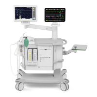
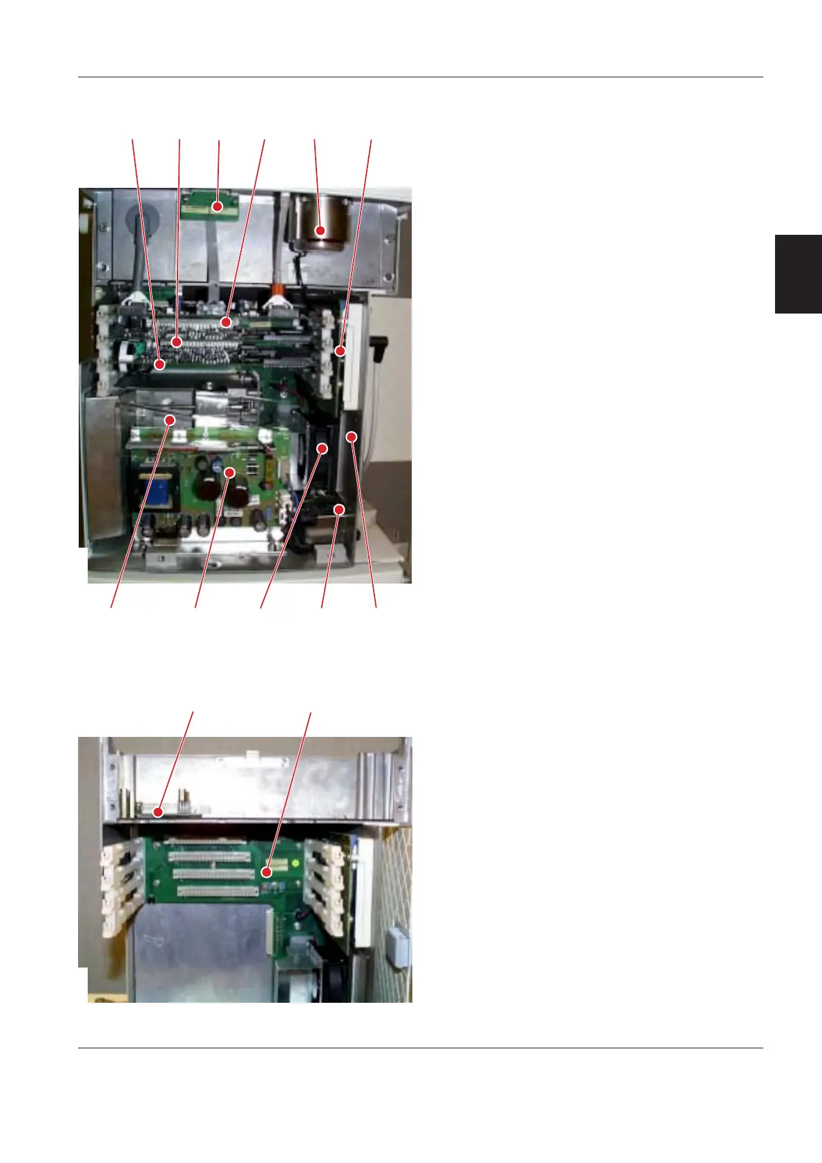
When the Patient Unit front cover is removed, the
following parts are accessible:
1. PC 1772 Monitoring.
2. PC 1771 Control.
3. PC 1784 Expiratory channel with the two
connected PC 1781 Inspiratory and Expiratory
Pressure Transducers.
4. Expiratory valve coil.
5. Module unit including PC 1775 Plug-and-play
back-plane.
6. AC/DC Converter.
7. Internal fan.
8. Mains supply inlet.
9. PC 1778 DC/DC & Standard connectors.
10. PC 1785 Expiratory channel connector.
11. PC 1789 Remote alarm connector (optional, not
shown in the illustration).
12. The PC boards, as listed above are directly or
indirectly connected to the PC 1770 Main back-
plane.
13. The gas modules, the O
2
cell and the safety valve
pull magnet are connected to the PC 1780
Pneumatic back-plane.
SVX9045
<=?@
6H 9; A
SVX9084
.

 Loading...