Introduction Servo-i Ventilator System
2 - 6 Service Manual Revision 02
2
SVX9014
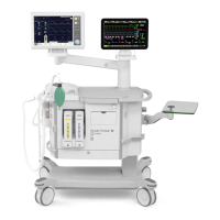
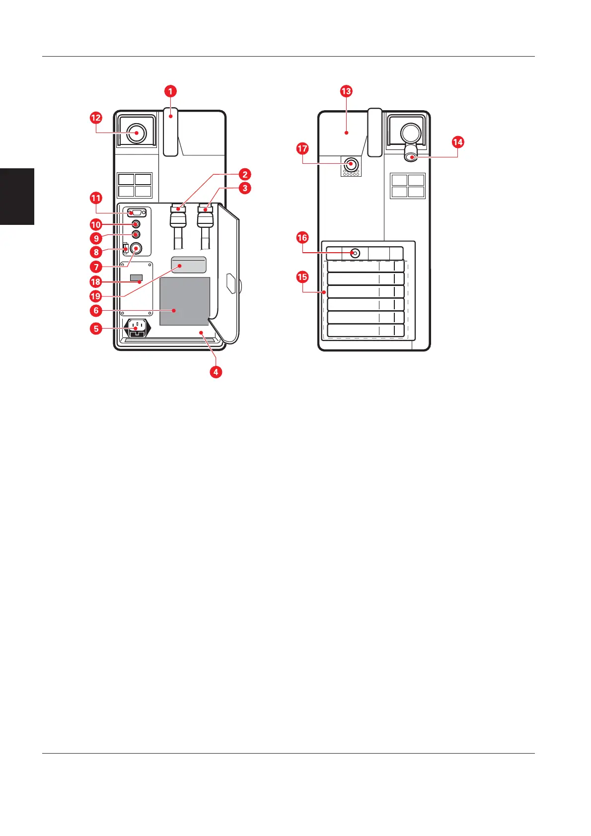
Patient Unit
The Patient Unit can be rotated on and pulled out of
the Servo-i Mobile cart. It can also be mounted onto
a Servo-i Holder or a Servo-i Shelf base.
Items accessible from the outside of the Patient Unit
are shown in the illustration above.
1. Handle.
2. Gas inlet for Air.
3. Gas inlet for O
2
.
4. Equipotentiality terminal.
5. Mains supply connector incl. fuses F11 and F12.
6. Internal fan with filter.
7. Connector for external +12V DC power supply.
8. Fuse F1 for external +12V DC power supply.
9. Optional connector.
10. Control cable connector.
11. 9-pole serial port for data communication
(RS- 232).
12. Expiratory outlet.
13. Inspiratory section cover.
14. Expiratory inlet.
15. Module unit for connecting optional modules,
e. g. up to six Battery modules.
16. Connector for Servo Ultra Nebulizer, Servo-i.
17. Inspiratory outlet.
18. Alarm output connector (optional).
19. Serial number label. The serial number stated on
this label is the ID number of the unit. This serial
number must always be refered to when ordering
service, spare parts, software updates/upgrades,
etc.
 Loading...