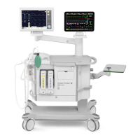
Description of functions Servo-i Ventilator System
3 - 4 Service Manual Revision 02
3
Nozzle unit
The plastic Nozzle Unit contains a valve diaphragm.
The valve diaphragm, controlled by the Inspiratory
Solenoid, regulates the gas flow through the Gas
Module.
The complete plastic nozzle unit must be replaced
during the 'Preventive maintenance'.
After replacement, allow the diaphragm to settle
during approx. 10 minutes before gas pressure is
connected to the Gas Module.
Inspiratory solenoid
The gas flow through the Gas Module is regulated by
the Inspiratory Solenoid via the Nozzle Unit.
The current supplied to the solenoid is regulated so
that the gas module will deliver a gas flow according
to the settings on the User Interface.
Gas module key
The Gas Modules are provided with a mechanical
key to prevent that the module is mounted in the
wrong slot.
The key consists of a plastic guide mounted
underneath the module and a corresponding guide
mounted in the patient unit.
ID PROM
Each Gas Module is provided with an ID-PROM. The
ID information can be read by the Servo-i System.
Connector muff
The Connector Muff connects the Gas Module
outlets to the Inspiratory Pipe inlet.
Inspiratory pipe
The Inspiratory Pipe leads the gas from the
Connector Muff to the Inspiratory Outlet.
The Inspiratory Pipe comprises:
• Housing and locking lever for the O
2
Cell with its
bacteria filter.
• Housing for the Safety Valve.
• Connection for measurement of inspiratory
pressure.
The pipe is provided with internal flanges with the
purpose to improve mixing of O
2
and Air.
O
2
cell
The O
2
Cell is mounted in a housing on the
Inspiratory Pipe and is protected by a bacteria filter.
SVX9015
Maintenance including exchange of bacteria filter
according to the User´s manual. The bacteria filter
must also be replaced during the 'Preventive
maintenance'.
The O
2
cell gives an output voltage proportional to
the partial pressure of oxygen inside the Inspiratory
pipe. At constant ambient pressure this output is
proportional to the O
2
concentration in percent.
In each O
2
cell, the output signal will stay at a fairly
constant level usually within 10–17 mV in normal air
and at standard barometric pressure during the life
time of the cell.
The life time of the cell is affected by the O
2
concentration. With a concentration (at the cell) in %
and expected cell life time in hours the following
applies at 25
o
C (77
o
F):
O
2
Conc. x Expected cell life = 500 000% hours.
The O
2
cell is automatically calibrated each time a
Pre-use check is performed (if O
2
is connected to the
ventilator).
If the ventilator has continually been in use for a long
time, the measured O
2
concentration may drop due
to normal degradation of the O
2
cell. This will activate
a nuisance alarm. For further information, refer to the
User's manual, chapter section 'O
2
cell adjustment'.
Note: Pre-use check is recommended to use to
calibrate the O
2
cell.
An ID PROM is integrated into each O
2
cell. Its ID
information and remaining lifetime can be read by the
Servo-i.
 Loading...