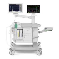
Description of functions Servo-i Ventilator System
3 - 10 Service Manual Revision 02
3
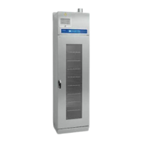
Module unit
Connection slots for 6 optional modules, e. g. Battery
modules or CO
2
Analyzer module.
Internal fan
The Internal Fan forces cooling air through the Patient
Unit. The cooling air flow inside the Patient Unit is
indicated in the 'Functional Main Block Diagram'.
The cooling air outlets are located in the expiratory
section.
The Internal Fan is controlled by the Temperature
Sensor in the O
2
cell connector via electronics on
PC 1775 Plug-and-play back-plane.
The fan will start with half effect at approx. 33 °C
(91 °F) and with full effect at approx. 43 °C (109 °F).
When the temperature drops below approx. 37 °C
(99 °F), the fan turns to half effect and when the
temperature drops below approx. 27 °C (81 °F),
the fan stops.
The air inlet is protected by a filter that must be
cleaned or replaced during the 'Preventive
maintenance'.
Optional PC board slots
Functional Main Blocks diagram marking: 'X'
For optional equipment, the Servo-i is equipped with
two extra PC-board slots.
The optional Alarm output connector (see below) is
mounted in one of the extra PC-board slots.
Alarm output connector (optional)
Functional Main Blocks diagram marking: 'A'
PC 1789 Remote alarm connector containing the
optional function 'Alarm output connector' is mounted
in the extra PC-board slot located below PC 1778
DC/DC & Standard connectors.
The Alarm output connector enables connection of an
external alarm signal system to the Servo-i System.
High and medium priority alarms are transferred, and
the alarm output signal is active as long as the audio
alarm is active on the ventilator.
The Alarm output connector has two contact
functions: NO (Normally Open) and NC (Normally
Closed). In an alarm situation the open contact will
close and the closed one will open. The contacts are
independent of polarity and can be used both with
AC and DC systems.
Pin configuration and signal names in P67 – Alarm
output connector can be found in chapter 'Diagrams'.
The 'Alarm output'- function must be enabled in the
configuration software.
For further information, refer to the 'Alarm output
connector – Reference Manual'
Battery modules (optional)
The Battery module is rated 12 V, 3.5 Ah. Battery
backup time is approx. 0.5 hour/battery. Up to six
backup Battery modules can be connected to the
Module unit.
SVX9019
Press the battery power symbol button to check the
battery status. The lit sections of the battery power
scale show remaining capacity.
• If no section is lit, the battery is fully discharged,
e.g. due to long storage time, and requires up to
12 hours/battery charging time.
• If one section is lit or flashing, the battery requires
approx. 3 hours/battery charging time.
The battery lifetime is limited and the batteries must
thus be replaced after 3 years. Manufacturing date
(year-week) is printed on the battery label.
Each battery includes an ID PROM. The ID
information can be read by the Servo-i System.
CO
2
Analyzer module (optional)
The CO
2
Analyzer module is an optional accessory
that is connected to the Module unit.
The CO
2
Analyzer option allows for continuous
monitoring shown in a waveform (capnogram) and
as numericals on the screen.
The CO
2
Analyzer module is, via a cable, connected
to a Capnostat sensor mounted on an airway
adapter at the Y-piece. The sensor uses a solid
state and IR based optical system with no moveable
parts. It measures the difference between a reference
light beam and one filtered for CO
2
wavelength.
The 'CO
2
Analyzer'- function must be enabled in the
configuration software.
Control cable
This Control Cable connects the Patient Unit and the
User Interface. The cable can be partly winded up
under a rubber cover on the rear of the User
Interface.

 Loading...