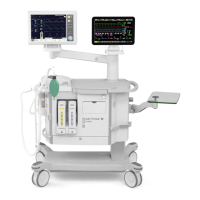
Disassembling and assembling Servo-i Ventilator System
4 - 2 Service Manual Revision 02
4
General
Disassembling of the main units in the Servo-i
System is described in this chapter. If not stated
otherwise, the assembling procedure is the reverse
of the described disassembling procedure.
The illustrations in the Servo-i Spare Parts List are
very useful as a guide when disassembling and
assembling the Servo-i System.
Preparations
Before disassembling or assembling the Servo-i:
• Set the On / Off switch on the User Interface to
Off.
• Disconnect the mains power cable.
• Disconnect the gas supplies (wall and/or tank).
• Disconnect Battery modules.
• Make sure that all gas conveying parts are
cleaned according to instructions in the
'Servo-i Ventilator System – User's manual'.
After any service intervention in the Servo-i,
perform a 'Pre-use check' according to
instructions in the 'Servo-i Ventilator System –
User's manual'.
Handling PC boards
The PC boards contain components that
are highly sensitive to static electricity.
Those who come into contact with
circuit boards containing sensitive
components must take certain
precautions to avoid damaging the
components (ESD protection).
When working with ESD sensitive components,
always use a grounded wrist band and grounded
work surface. Adequate service tools must also be
used.
PC boards (spare parts) must always be kept in
protective packaging for sensitive electronic device.
PC boards must not be inserted or removed while
the mains power or battery power is applied to the
PC boards.
Remove and insert the PC boards very carefully to
avoid damage to the connectors.
Replacing PC boards
The Servo-i software is distributed on different
subsystems, located on the following PC boards:
• PC 1771 Control
• PC 1772 Monitoring
• PC 1784 Expiratory Channel
• PC 1777 Panel.
When delivered as spare parts, these PC boards are
equipped with a 'System SW version' that may differ
from the version on the unit to be repaired.
To keep the 'System SW version' used prior to the
PC board replacement, a 'SW version update card'
with the applicable 'System SW version' must be
available for re-installation purposes.
For functionality enhancement, the latest released
version of the System SW is always recommended.
Before installing a new 'System SW version' on a unit,
ensure that the software is fully compatible with all
HW-, SW- and mechanical components in the unit.
If any compatibility conflicts are apparent this will be
noted on the 'MAQUET Critical Care SW download'
web site.
Assembling guidelines
The Servo-i system specifications allow unit operation
also during patient transportation. All parts of the
User Interface and the Patient Unit assembled with
screws and nuts are therefore tightened with a
specified torque and secured with threadlocking
adhesives.
In order to maintain these specifications over time,
it must be ensured that after any service intervention
removed parts are re-assembled and secured
according to instructions. Make sure to follow the
guidelines stated below.
Tightening torque
• Thread size M3: 0.95 ±0.05 Nm
• Thread size M4–M6: 3.1 ±0.1 Nm.
Threadlocking adhesives
• Electrolube Bloc'Lube BLV15ML® on threads in
contact with PC boards.
• Loctite 243® on all other threads.
Note: Threadlocking adhesive is not required on
Heli-Coil® screw thread inserts as these screw
thread-inserts have a self-locking function.

 Loading...