123457, 70705-9-9521 Ä-St.1 Montageanleitung GC 302 R 5
1
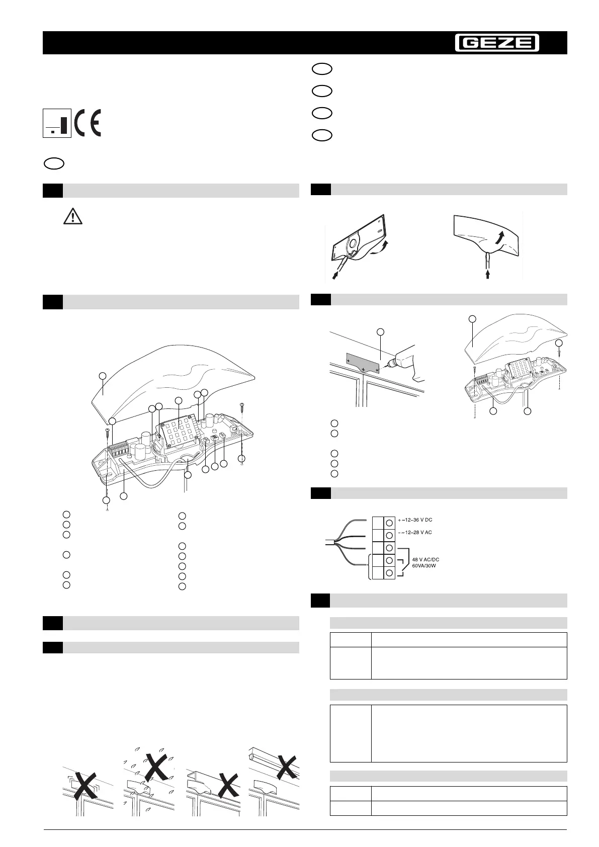
Safety Instructions
The unit may only be connected to a protection low-voltage system
with safe electrical separation. The unit may only be opened and
repaired by the supplier. Never touch any electronic components of
the sensor.
4
Displays on the Sensor
Red LED
Recess for fastening
the sensor
Floor plate
Cable feed-through
DIP switch (addressing)
Key [<]
Key [>]
8
9
10
11
12
13
7
Cover
Plug-in screw terminal
Grid for swivelling
the radar module
Grid for tilting
the radar module
Radar double field module
Green LED
5
4
2
3
6
1
3.2 Opening the housing
– The sensor must be mounted on a flat surface
(avoid vibrations)
– The sensor must be protected from rain and snow
– Objects (e.g. plants, flags, fans etc.) must not extend into the detection area
– The sensor must not be obscured by covers/signs
– Fluorescent tubes should not be placed in the immediate vicinity of the detection
area
3
Installation
3.1 Installation instructions
3.4 Electrical connections
Green LED
– Indicates parameter or parameter level through
frequency of flashing (with key configuration)
– Flashes briefly:
– When key configuration mode is exited
– When the sensor has received the command from
the remote control
LED red Lights up in the event of detection
Green LED Lights up when SMD is active
BEFORE installation AFTER installation
Start-up phase
Configuration
Operation
Red LED Lights up during startup for 3 s
Green LED
Afterwards, the green LED flashes a few times and indicates the
software version (the sensor is already functional and
programmable)
I
nstallation instructions
GB
GC 302 R
Quality
international
l
evel
E
N ISO
9
001
Radar motion detector with direction recognition as opening sensor
for automatic doors.
3.3 Mounting
2
Description of the Sensor
1
1
5
11
2
13
7
6
4
8
10
8
12
3
Affix drilling jig to wall/ceiling and drill holes according to instructions
Route cable through the appropriate opening in the floor plate –
make sure length is sufficient for wiring
Fasten sensor
Connect cable (according to type plate or chap. 3.4)
Click cover onto floor plate
2
3
4
5
1
2
3
4
5
9
M
ontageanleitung (Original) .......................... 1–4
Installation instructions (Translation)............ 5– 8
Instructions de montage (Traduction) ........ 9–13
I
struzioni di montaggio (Traduzione) ........ 14–16
IT
F
R
GB
DE

 Loading...