4
6
5
4
5
X
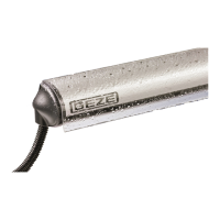
GC 334
SETTINGS
DOOR SAFETY CHECK
CALIBRATION
IMPORTANT: Test the good
functioning of the installation
before leaving the premises.
If necessary, position spots
closer to or away from the door
and relaunch a calibration.
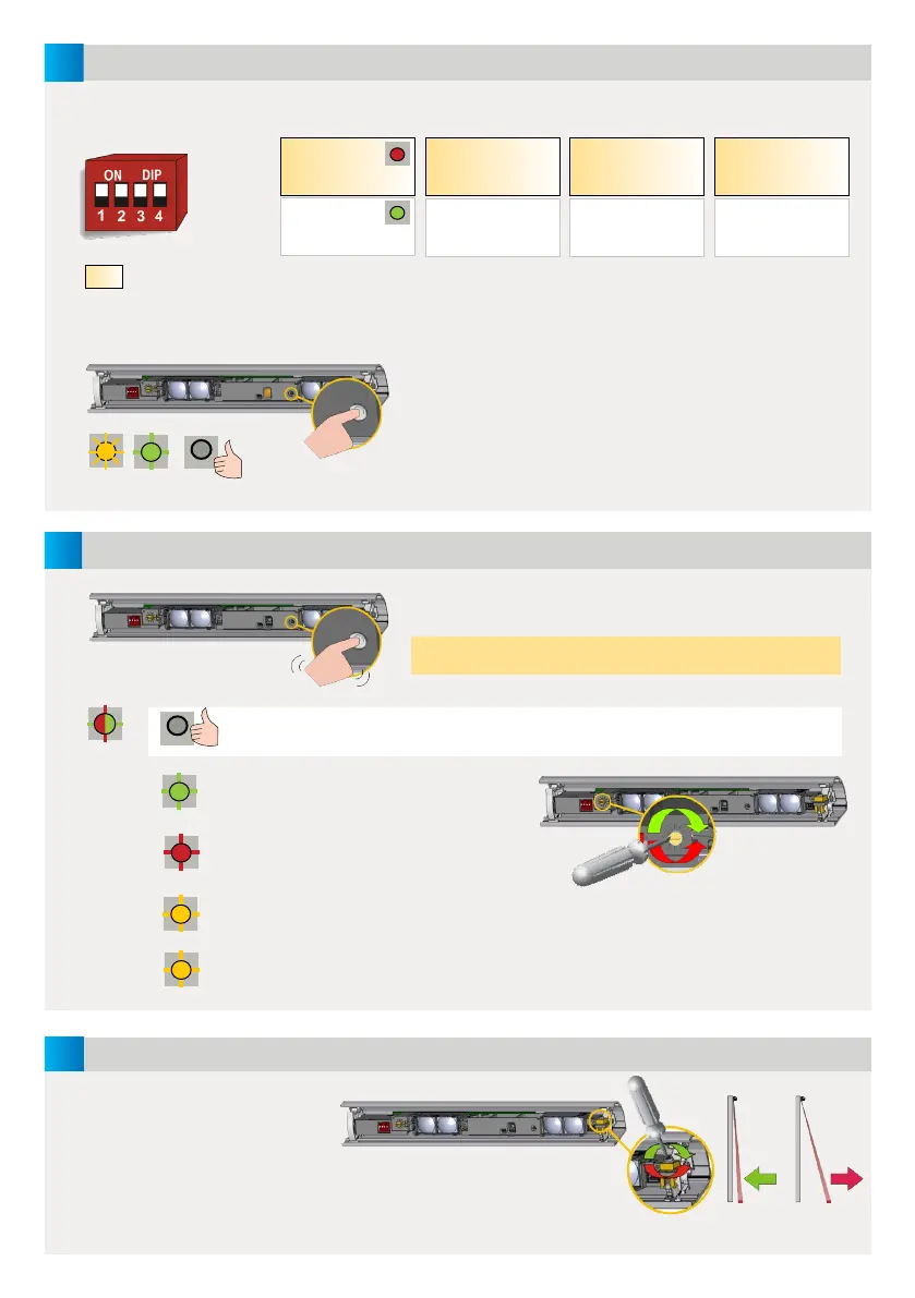
After changing a DIP-switch, the orange LED flashes.
A LONG push on the push button of the MASTER
confirms the settings of ALL MODULES.
Afterwards, a number of green flashes (x) indicates
the number of connected modules.
A SHORT push on the button of the MASTER launches a
calibration on ALL MODULES.
Do not stand in the detection field!
When the LED is off on all modules, the detection zone is OK.
The detection zone is too short:
turn the screw clockwise.
The detection zone is too long:
turn the screw anticlockwise.
Step out of the detection field.
If necessary, change angle or switch off background (DIP 3 = OFF).
Launch a new calibration.
The flashing speed of
the LED increases when
approaching the optimal
position.
MOUNTING
SIDE
FREQUENCY BACKGROUND
UNCOVERED
ZONE
RELAY 1
OPENING SIDE
RELAY 2
CLOSING SIDE
FREQ A
FREQ B
ON
OFF
HIGH*
LOW
ON
OFF
LED during detection:
R1 > RED
R2 > GREEN
Set different
frequencies on
modules close to
each other.
Not enough background
reflectivity: switch to OFF
Approximate values at 2 m:
high= 40 cm, low = 15 cm
RED-GREEN
OFF
GREEN
RED
ORANGE
ORANGE GREEN OFF
FACTORY VALUE
* Recommended for most applications.
Mounting height > 2.7 m: set to LOW for
EN 16005 and DIN 18650-conformity.
 Loading...