11
Table 7.1 Technical data
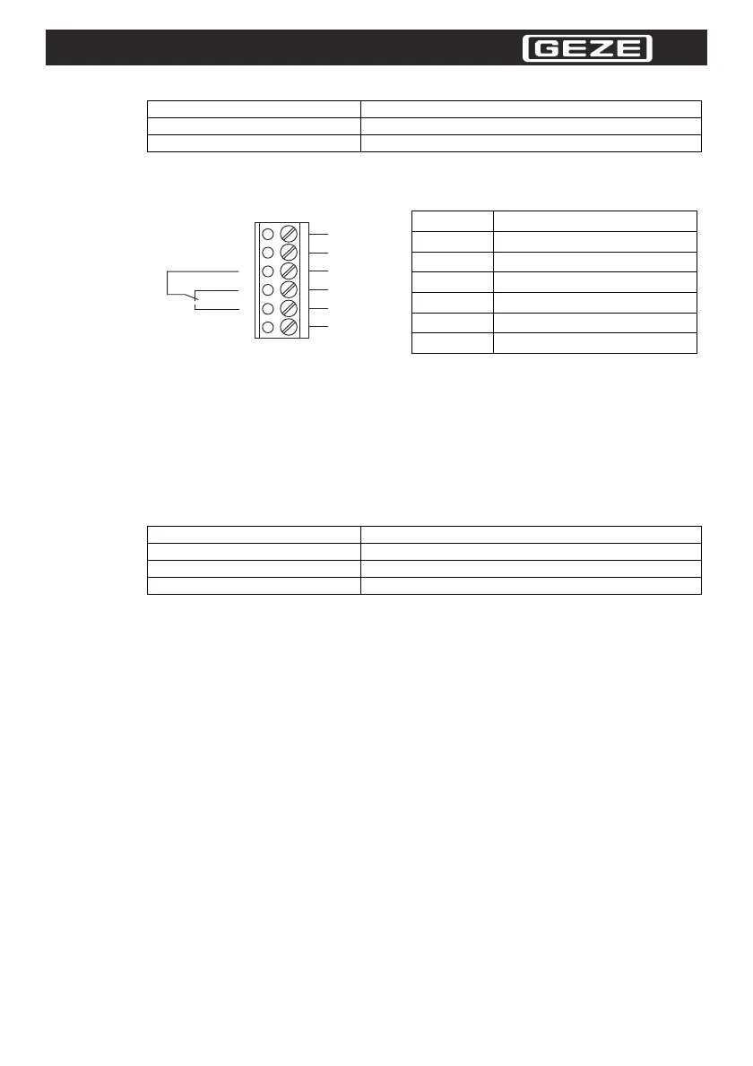
7.1 Assignment of the Connections
Explanation:
Relay:
• Relay is inactive during detection
• Relay is active in free detection field
Test input:
• Test input is inactive at:U_low = -3 V ... +5 VDC
• Test input is active at: U_high = +11 V ... +24 V DC ± 20 %
8 Components of GC 335
Table 8.1 Components of GC 335
9 Disposal, Repair, Maintenance
9.1 Disposal
Dispose of the useless device in keeping with the applicable national legal regulations.
For example, take the sensor to a pertinent collection point for electronic waste.
9.2 Repair
Defective device may be repaired by the manufacturer only.
9.3 Servicing
Observe the applicable national regulations for servicing.
The sensor is maintenance-free by and large.
Nonetheless, check the technical safety of the sensor system in regular intervals, watching out for dam-
age of the housing in particular.
If it has to be assumed that a safe operation is no longer possible, the sensor system has to be shut
down and secured against unintentional operation.
Check the sensor for soiling occasionally. In order to clean the sensor, use a dry or moist soft cloth to
wipe across the sensor in regular intervals. This action will ensure an optimal function.
The housing is made of plastic. For this reason avoid contact with acetone and detergents containing
solvents.
Material
Housing Aluminum / ABS
Light exit PMMA
Pin Assignment
1 GND (0 V)
2 UB +24 VDC ± 20 %
3 Relay - center contact
4 Relay breakcontact
5 Relay make contact
6 Test input
Part Numbers Description
128074 GC 335, MASTERMODUL
128065 GC 335, SLAVEMODUL
120190 Prüfkörper GC 335
 Loading...